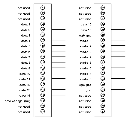
Terminal Numbering and Input Functions
User connections are made to a standard screw terminal strip The rigid wiring system permits module insertion or removal without disturbing the wiring.
Terminal numbering and input functions are shown on the following illustration.
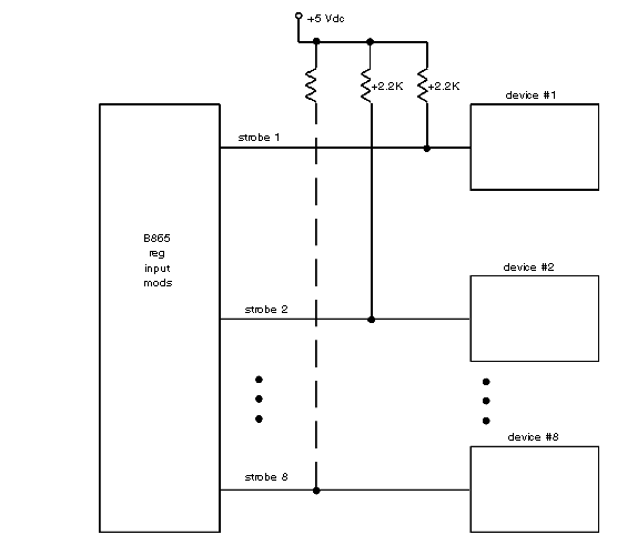
Pull-up Resistor Connection
Resistive pull-ups of 2.2 kΩ 10% for each strobe line must be provided.This is required on active devices only. Thumb wheel switches, for example, do not require the addition of pull-up resistors.
The recommended location for the pull-up resistors is at the device end of the circuit. However, they will work at the module end as well.
The following illustration shows a typical circuit setup.
Strobe lines for the B865 module are true-low. The opposite is the case in other Modicon I/O modules. Therefore, when multiple thumb wheel inputs require diode isolation, the polarity of the diodes may have to be reversed.

