Using the Configuration Tab
Original instructions
Configuration Screen
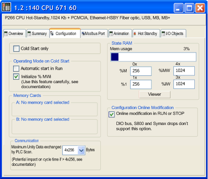
Change values using the Configuration tab of the editor:
Description
Configuration tab:
Item
Option
Value
Description
Cold Start Only
x
Enables the Cold Start Only feature.
Operating Mode On Cold Start
Automatic start in Run
x
Determines the operating condition during Cold Start
Initialize %MWi
x
Memory Cards
A:
N/A
Displays the configuration in the PCMCIA Slots
B:
N/A
Communication
By default, the bandwidth is 4x256 bytes, supported by the OS versions prior to V2.80 for the CPU and V4.60 for the NOE.
The maximum data volume exchanged each cycle between the NOE and CPU modules
For Quantum processors:
  • 140 CPU 311 10
  • 140 CPU 534 14
  • 140 CPU 434 12
4x256
4x1024
For Quantum processors:
  • 140 CPU 651 50
  • 140 CPU 651 60
  • 140 CPU 652 60
  • 140 CPU 658 60
  • 140 CPU 671 60
  • 140 CPU 672 60
  • 140 CPU 672 61
  • 140 CPU 678 61
4x256
4x1024
8x1024
12x1024
State RAM
Mem usage
1.
A bar displays percent of memory used.
%M-0x
2.
Size of the different memory areas
Note: The values for %IW and %MW have to be divisible by 8.
%MW-4x
2.
%I-1x
2.
%IW-3x
2.
Viewer
N/A
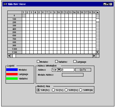
Opens the State RAM Viewer tab, which displays the allocation of used memory. (See the illustration following.)
Configuration Online Modification
Online modification in RUN or STOP
x
This check box allows to:
  • Add or delete discrete or analog modules,
  • Modify Parameters
NOTE: These modifications can be done in RUN mode.
1. The value (expressed as a percentage and displayed on the scale) depends on the memory usage of the Hot Standby configuration.
2. Enter the appropriate values. All values depend on Hot Standby configuration.
Cold Start Only
If checked, this option forces the cold start of the application, instead of the normal warm start.
By default, the Cold Start Only option is unchecked.
The Cold Start Only option is only supported on High End PLC since V2.7.
An application using this functionality will not be:
NOTE: The Cold Start Only check box is present only if the current selected PLC can support it.
Automatic Start in RUN
The enabling of this option automatically changes the PLC to Run mode on cold start.
Two types of start:
WARNING
UNWANTED APPLICATION RUN ON PLC COLD START
With the Automatic start in RUN option enabled, the following events will trigger the run of the application on cold start:
  • Inserting the PCMCIA card when the PLC is powered
  • Replacing the processor while powered
  • Unintentional or careless use of the reset button
  • Powering up a PLC with a defective battery after a power outage
To prevent the run of the application on cold start, use the switch on the front panel of the processor.
Failure to follow these instructions can result in death, serious injury, or equipment damage.
Initialize %MWi
On application download:
On cold start or after inserting the PCMCIA memory card:
Communication
When the protocol under TCP/IP is used (OFS or Control Expert), it is possible to configure the maximum volume of data that can be exchanged each cycle between the CPU and the NOE modules using the Maximum Unity Data exchanged by PLC Scan option.
This functionality is only supported on CPU modules with OS version 2.80 or higher, and on NOE modules with OS version 4.60 or higher.
The bandwidth set is valid between the CPU and all existing NOE modules. It is not possible to set different bandwidths for each of the modules.
Increasing this bandwidth has an impact on the cycle time of the controller (2 ms per kbytes exchanged). This impact is proportional to the amount of data actually exchanged and not the bandwidth configured. So, if the channel is set to the maximum, but not used, the impact on cycle time will be negligible.
State RAM memory
The State RAM bar chart allows you to know the size of the State RAM memory used in your project in relation to the maximum memory size.
Using the State RAM Viewer
The State RAM Viewer dialog:
Each cell in the grid represents an address location and displays the entity stored in that location. The contents of the grid may be changed by selecting options in either of two filters:
  1. Memory used grid options:
    Select one—or all—of the three options (using the check box) and one to three bar graphs appear.
    • Modules
      Indicates the topological address used in the modules. Address appears as a bar graph in the grid.
    • Language
      Indicates the topological address used in the program. Address appears as a bar graph in the grid.
    • Variables
      Indicates the topological address used in the variables. Address appears as a bar graph.
  2. Memory Area options:
    Using this option, you designate a state RAM address. Select one of four reference types.
    • %M
    • %I
    • %IW
    • %MW
Your choice appears in the Address field of the Address Information area.
Online Configuration Modification
On PLCs supporting this functionality a check box is activated and appears in the CPU Editor.
The Configuration Online modification is only available on certain types of PLCs if the Online Modification in RUN or STOP check box is selected.