|
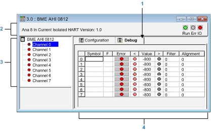
Description of the Analog Module Debug Screen
|
|


|
Original instructions
|
|
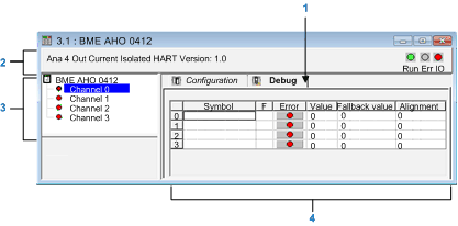
Description of the Analog Module Debug Screen
|
|
|
Original instructions
|
|
Address
|
Element
|
Function
|
|---|---|---|
|
1
|
Tabs
|
The tab in the foreground indicates the mode in progress (Debug in this example). Each mode can be selected by the corresponding tab. The available modes are:
|
|
2
|
Module area
|
Specifies the shortened name of the module.
In the same area there are 3 LEDs which indicate the status of the module in online mode:
|
|
3
|
Channel area
|
Is used:
|
|
4
|
Viewing and control area
|
Displays the value and status for each channel in the module in real time. The symbol column displays the symbol associated with the channel when it has been defined this (from the variable editor).
This area provides direct access to channel by channel diagnostics when these are inoperative (indicated by error column LED, which turns red).
|
