|


|
Original instructions
|
|
|
Original instructions
|


|
Label
|
Pattern
|
Indication
|
|---|---|---|
|
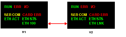
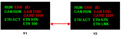
RUN (green): operational state
|
on
|
PLC functioning normally, program running
|
|
flashing
|
PLC in STOP mode or blocked by a software detected error
|
|
|
off
|
PLC not configured (absent, invalid, or incompatible application)
|
|
|
ERR (red): detected error
|
on
|
Processor or system detected error
|
|
flashing
|
|
|
|
off
|
Normal status (no internal detected errors)
|
|
|
I/O (red): input/output status
|
on
|
|
|
off
|
Normal status (no internal detected errors)
|
|
|
SER COM (yellow): serial data status
|
flashing
|
Data exchange on the serial connection in progress (receiving or sending)
|
|
off
|
No data exchange on the serial connection
|
|
|
CARDERR (red): memory card detected error
For further information, see project backup management for Modicon M340 PLCs
|
on
|
|
|
off
|
|
|
|
CAN RUN (green): CANopen operations
|
on
|
CANopen network operational
|
|
rapid flashing (on for 50 ms, off for 50 ms, repeating)
|
Automatic detection of data flow or LSS services in progress (alternates with CAN ERR)
|
|
|
slow flashing (on for 200 ms, off for 200 ms, repeating)
|
CANopen network pre-operational
|
|
|
1 flash
|
CANopen network stopped
|
|
|
3 flashes
|
downloading CANopen firmware
|
|
|
CAN ERR (red): CANopen detected errors
|
on
|
CANopen bus stopped
|
|
rapid flashing (on for 50 ms, off for 50 ms, repeating)
|
Automatic detection of data flow or LSS services in progress (alternates with CAN RUN)
|
|
|
slow flashing (on for 200 ms, off for 200 ms, repeating)
|
CANopen configuration not valid
|
|
|
1 flash
|
At least one of the detected error counters has reached or exceeded the alert level
|
|
|
2 flashes
|
A guard event (NMT-slave or NMT-master) or a heartbeat event has taken place
|
|
|
3 flashes
|
The SYNC message was not received before the end of the communication cycle period
|
|
|
off
|
No CANopen detected error
|
|
|
off
|
No communication activity
|
|
|
ETH STS (green): Ethernet communication status
|
on
|
Communication OK
|
|
2 flashes
|
Invalid MAC address
|
|
|
3 flashes
|
Ethernet link not connected
|
|
|
4 flashes
|
Duplicate IP address
|
|
|
5 flashes
|
Waiting for a server IP address
|
|
|
6 flashes
|
Secure and safe mode (with default IP address)
|
|
|
7 flashes
|
Configuration conflict between rotary switches and internal configuration
|
|
|
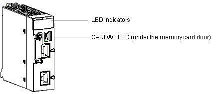
CARDAC (green): memory card access
Note: This LED is located under the memory card door.
|
on
|
Access to the card is enabled
|
|
flashing
|
Activity on the card; during each access, the card LED is set to OFF, then back to ON
|
|
|
off
|
Access to the card is disabled. It is possible to extract the card after the access to the card has been disabled by generating a rising edge on the bit %S65.
|
|
Label
|
Pattern
|
Indication
|
|---|---|---|
|
ETH ACT (green): Ethernet communication (transmission/reception) activity
|
on
|
Ethernet link detected: no communications activity.
|
|
off
|
No Ethernet link detected.
|
|
|
flashing
|
Ethernet link and communications activity detected.
|
|
|
ETH 100 (green): Ethernet transmission speed
|
on
|
Ethernet transmission at 100 Mbit/s (Fast Ethernet).
|
|
off
|
Ethernet transmission at 10 Mbit/s (Ethernet) or no link detected.
|
|
Label
|
Pattern
|
Indication
|
|---|---|---|
|
ETH ACT (green): Ethernet communication (transmission/reception) activity
|
on
|
Communication activity detected.
|
|
off
|
No communication activity detected.
|
|
|
ETH LNK (green): Ethernet link status
|
on
|
Ethernet link detected.
|
|
off
|
No Ethernet link detected.
|
|
|
off
|
No communication activity
|
