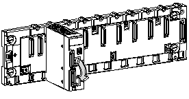
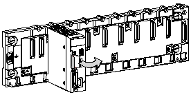
All BMX P34 •••• processors require a memory card.
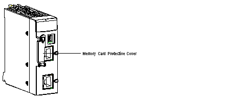
The following illustration shows the memory card slot on a BMX P34 •••• processor with a protective cover in place:
Only Schneider memory cards are compatible with BMX P34 •••• processors.
Schneider memory cards use Flash technology and do not require a battery. These cards can support about 100,000 write/delete cycles (typical).
Three models of memory card are available:
-
The BMX RMS 008MP card, used to save application and Web pages.
-
The BMX RMS 008MPF card, used to save applications and Web pages as well as to store user files created by the application with the file management function blocks (or files transferred through FTP). The available size for user files in the file system partition is 8 MB (Data Storage area).
-
The BMX RMS 128MPF card, used to save applications and Web pages as well as to store user files created by the application with the file management function blocks (or files transferred through FTP). The available size for user files in the file system partition is 128 MB (Data Storage area).
NOTE: The web pages are Schneider Electric pages and cannot be modified.
NOTE: The BMX RMS 008MP card is supplied with each processor, the other ones must be ordered separately.
Memory Card Characteristics
The following table shows the main characteristics of the memory cards.
|
Memory Card Reference
|
Application Storage
|
Data Storage
|
|
BMX RMS 008MP
|
Yes
|
No
|
|
BMX RMS 008MPF
|
Yes
|
8 MB
|
|
BMX RMS 128MPF
|
Yes
|
128 MB
|
NOTE: The size shown above for the Data Storage area is the maximum recommended size for user files, although file storage is still possible until the global file system partition is full. The risk of going over this recommended maximum is that sufficient free space may not be available for a firmware upgrade, in this case it would be necessary to delete some user files.
The compatibility of the two memory cards is as follows:
NOTE: The memory card is formatted for use with Schneider Electric products. Do not attempt to use or format the card in any other tool. Doing so will prevent program and data transfer usage in a Modicon M340 PLC.
NOTE: For further information about Ethernet services provided by memory cards, see the
Modicon M340 Memory cards page in the Ethernet Communication part.
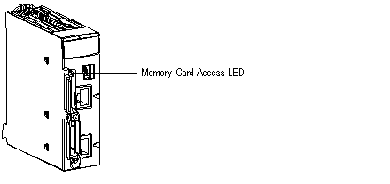
A memory card access LED is included on all Modicon M340 processors. This LED informs the user of the memory card’s status for its removal.
The following illustration shows the physical location of the memory card access LED:
This LED is green and has several different states:
-
On: the card is recognized and the processor has access to it,
-
Flashing: the LED goes off each time the processor accesses it and comes on again at the end of access,
-
Off: the card may be removed as the processor has no access to it.
NOTE: A rising edge on the bit %S65 finishes the current actions, disables access to the card, then switches off the CARDAC LED. As soon as this LED is off, the card can be removed.
NOTE: The memory card access LED is only visible if the cover is open.
NOTE: The red CARDERR LED shows that either the memory card is in error or the memorized application is different from the one processed by the processor. It is located near the top of the processor front panel.
LED States on Power Cycle
The following table presents the different states of the PLC, memory card access LED and CARDERR LED on a power cycle or a PLC reset.
|
|
PLC/memory card behavior
|
PLC state
|
Memory card access LED
|
CARDERR LED
|
|
No memory card
|
-
|
No configuration
|
OFF
|
ON
|
|
Memory card not OK
|
-
|
No configuration
|
OFF
|
ON
|
|
Memory card without project
|
-
|
No configuration
|
ON
|
ON
|
|
Memory card with a non-compatible project
|
-
|
No configuration
|
ON
|
ON
|
|
Memory card with a compatible project
|
Error detected when the restore project from memory card to the PLC RAM
|
No configuration
|
Flashing during transfer
Finally ON
|
ON
|
|
Memory card with a compatible project
|
No Error when the restore project from memory card to the PLC RAM
|
|
Flashing during transfer
Finally ON
|
ON durring transfer
Finally OFF
|
Memory Card Insertion Procedure
The following illustration shows the procedure for inserting a memory card into a BMX P34 •••• processor.
|
Step
|
Description
|
Illustration
|
|
1
|
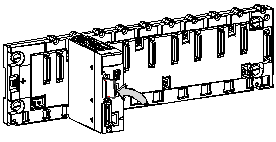
Open the processor’s protective cover by pulling the cover towards you.
|
Opening the cover:
|
|
2
|
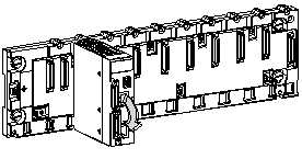
Insert the memory card into its slot by pushing it right in.
Result: The card should now be clipped into its slot.
Note: Insertion of the memory card does not force an application restore.
|
Inserting the memory card:
|
|
3
|
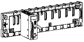
Close the memory card protective cover.
|
|
Memory Card Removal Procedure
Before removing a memory card, a rising edge on bit %S65 has to be generated to ensure the information consistency. When the CARDAC LED is off, then it is possible to extract the card. There is a risk of inconsistency or loss of data if the extraction is done without the management of the bit %S65. The following illustration shows the procedure for removing a memory card from a BMX P34 •••• processor.
|
Step
|
Description
|
Illustration
|
|
1
|
Open the processor’s protective cover by pulling the cover towards you.
|
Opening the cover:
|
|
2
|
Push the memory card in its slot.
Result: The card should unclip from its slot.
|
Pushing the memory card in its slot:
|
|
3
|
Remove the card from its slot.
Note: The CARDERR LED is on when the memory card is removed from the processor.
|
Removing the memory card:
|
|
4
|
Close the protective cover.
|
|
Before removing a memory card, a rising edge on bit %S65 has to be generated to ensure the information consistency. When the CARDAC LED is off, then it is possible to extract the card. There is a risk of inconsistency or loss of data if the extraction is done without the management of the bit %S65.The following table shows the procedure for updating an application in a processor using a master memory card.
|
Step
|
Description
|
|
1
|
Put the PLC in STOP.
|
|
2
|
Set bit %S65 to 1 and check that the CARDAC LED is off.
|
|
3
|
Remove the currently used memory card, which includes the old application.
|
|
4
|
Insert the master memory card in the the processor.
|
|
5
|
Press the RESET button on the power supply.
Result: the new application is transferd to internal RAM.
|
|
6
|
Remove the master memory card.
|
|
7
|
Insert the memory card with the old application in the the processor.
|
|
8
|
Do a backup command.
|
|
9
|
Put the PLC in RUN mode.
|
%SW146-147: those 2 system words contain the unique SD card serial number (32bits). If there is not an SD card or an unrecognized SD card, the 2 system words are set to 0. This information can be used to protect an application against duplication: the application is able to check the value of serial number and can go to halt (or other convenient action) if it is different from the initial one. Thus, this application cannot run on a different SD card.
With Control Expert, the application must be read-protected. To do that, uncheck the Upload information in the Project settings.
NOTE: to enforce the protection, you can encrypt the value of the serial number used in the comparison.
NOTE: the complete SD card identification comprises several parameters including the product serial number (32bits).
To keep the memory card in normal working order, the following precautions should be taken:
-
Avoid removing the memory card from its slot when the processor is accessing it (green access LED on or flashing).
-
Avoid touching the memory card connectors.
-
Keep the memory card away from electrostatic and electromagnetic sources as well as heat, sunlight, water, and moisture.
-
Avoid impacts to the memory card.
-
Before sending a memory card by post, check the postal service’s security policy. In some countries the postal service exposes mail to high levels of radiation, as a security measure. These high levels of radiation may erase the contents of the memory card and render it unusable.
-
If a card is extracted without generating a rising edge of the bit %S65 and without checking that the CARDAC LED is off, there is a risk of loss of data (file, application).
 WARNING
 WARNING