|
Fitting of Processors
|
|
|
Original instructions
|
 DANGER DANGER |
|
HAZARD OF ELECTRIC SHOCK
Disconnect all power sources before installing the processor.
Failure to follow these instructions will result in death or serious injury.
|

|
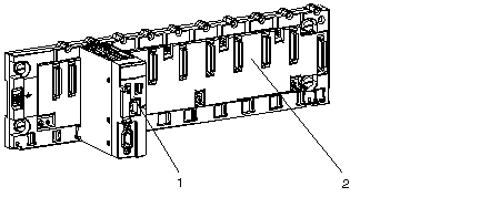
Number
|
Description
|
|---|---|
|
1
|
Processor
|
|
2
|
Standard rack
|
 WARNING WARNING |
|
UNEXPECTED EQUIPMENT OPERATION
Ensure that the correct memory card is installed before plugging a new processor on the rack. An incorrect card could lead to unexpected system behavior.
Refer to %SW97 to check the status of the card.
Failure to follow these instructions can result in death, serious injury, or equipment damage.
|
|
Step
|
Action
|
Illustration
|
|---|---|---|
|
1
|
Verify that power is OFF and make sure that the memory card is correct.
|
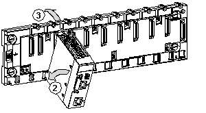
The following illustration describes steps 1 and 2:
 |
|
2
|
Position the locating pins situated at the rear of the module (on the bottom part) in the corresponding slots in the rack.
Note: Before positioning the pins, make sure that you have removed the protective cover.
|
|
|
3
|
Swivel the module towards the top of the rack so that the module sits flush with the back of the rack. It is now set in position.
|
|
|
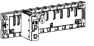
4
|
Tighten the mounting screw to ensure that the module is held in place on the rack.
Tightening torque: 0.4...1.5 N•m (0.30...1.10 lbf-ft).
|
The following illustration describes step 3:
 |