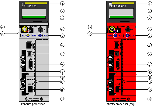
The figure shows a standard High End module and its components.
1
model number, module description, color code
2
lens cover (open)
3
LCD display (here covered by the lens cover)
4
key switch
5
keypad (with 2 red LED indicators)
6
modbus port (RS-232) (RS-485)
7
USB port
8
Modbus Plus port
9
PCMCIA slot A (depends on CPU reference)
10
PCMCIA slot B
11
LED indicators (yellow) for Ethernet communication
12
Ethernet port
13
battery (user installed)
14
reset button
15
2 screws
NOTE: Quantum High End processors are equipped with one PCMCIA slot (B) or two PCMCIA slots (A and B) in which to install Schneider PCMCIA cards (other cards are not accepted).
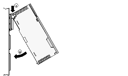
Mounting the module onto the central back plane:
1
Hang the module.
2
Screw the module to the back plane. 
