|
Mounting Quantum Modules
|
|


|
Original instructions
|
|
Mounting Quantum Modules
|
|
|
Original instructions
|
 CAUTION CAUTION |
|
POSSIBILITY OF MODULE DAMAGE
The inappropriate use of solvents, cutting oils, bug sprays and similar chemicals may cause the breakdown of module cases or terminal blocks.
Failure to follow these instructions can result in injury or equipment damage.
|
 WARNING WARNING |
|
UNEXPECTED SYSTEM BEHAVIOR - CPU HOT SWAP CONSEQUENCES
Do not Hot Swap Quantum CPU.
Failure to follow these instructions can result in death, serious injury, or equipment damage.
|
|
CAUTION |
|
UNINTENDED EQUIPMENT OPERATION
Hot swapping an I/O module can generate an error code causing the module to stop functioning.
Failure to follow these instructions can result in injury or equipment damage.
|
|
Step
|
Action
|
|---|---|
|
1
|
If required for the application, select and install a 20 mm or 125 mm mounting bracket to the rack using standard hardware.
Front view:
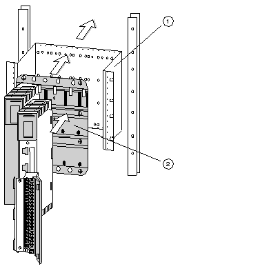 1Mounting bracket 2Rack |
|
2
|
Select and install the appropriate rack to the mounting bracket using standard hardware and remove the plastic rack connector dust covers.
|
|
Step
|
Illustration
|
Action
|
|---|---|---|
|
1
|
Side view:
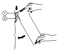 1Module Hooks 2I/O Bus Connector |
Mount the module at an angle on to the two hooks located near the top of the rack.
|
|
2
|
Swing the module down to make an electrical connection with the rack I/O bus connector.
|
|
|
3
|
Side view:
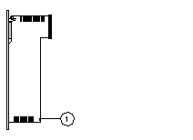 1Mounting screw |
Tighten the screw at the bottom of the module to fasten it to the rack.
Note: The maximum tightening torque for this screw is 2-4 in-lbs (0.23 - 0.45 Nm).
|
