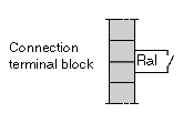
The alarm relay located in each supply module has a potential free contact, which can be accessed on the module’s screw connection terminal block.
Illustration:
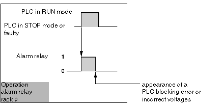
Alarm relay of the module situated on the rack supporting the processor (rack 0)
When operating normally, with the PLC in RUN mode, the alarm relay is activated and its contact is closed (state 1). Whenever the application is stopped, even partially, when a "blocking" error appears, when there are incorrect output voltages or power disappears, the relay falls back and its associated contact opens (state 0).
Illustration:
If this function is absolutely imperative for the proper operation of the installation, the alarm relay of the power supply module can be replaced by the use of an alarm relay output on the X Bus or the FIPIO bus. In order to achieve this, this output should be:
-
a relay output,
-
configured with fallback to 0 (default configuration),
-
initialized at state 1 when the application program starts executing.
When configured in this way, the relay output will behave in the same way as the alarm relay controlled by a TSX P57/TSX H57 processor.
Alarm relay for modules on the other racks (1 to 7)
Once the module has been switched on and if the output voltages are correct, the alarm relay is activated and the contact is closed (state 1).
If the power disappears, or if the output voltages are incorrect, the relay falls back (state 0).
These modes of operation allow these contacts to be used in fail-safe external circuits, as, for example, the automatic control of pre-actuator supplies, or the transmission of information.


 CAUTION
 CAUTION