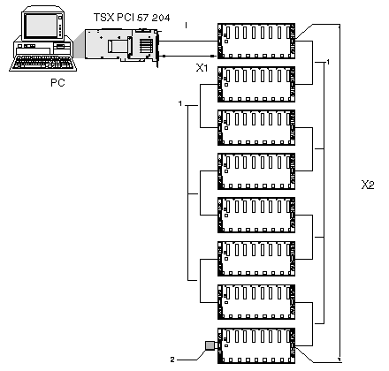
It is possible to build a PLC station with an Atrium processor using extendable racks: TSX RKY 4EX/6EX/8EX/12EX.
Building Using Extendable Racks
Extendable racks can be used to build a PLC station that contains a maximum of:
|
Station
|
Number of racks
|
|
For a TSX PCI 57 204 station
|
|
|
For a TSX PCI 57 354 station
|
|
Diagram:
-
(1) The same station can contain 4, 6, 8 and 12 position racks that are interconnected by
X-Bus extension cables (labeled 1).
-
NOTE: The cumulative length (X1+X2) of all the TSX CBY..0K cables used in a PLC station must never exceed 100 meters. For applications which require a distance of more than 100 meters between racks, an extension module allows the extension of two X-Bus segments from the rack which is supporting the Atrium processor virtually, to a maximum distance of 250 meters, each X-Bus segment having a maximum distance of 100 meters.
Racks are connected by means of TSX CBY••0K X-Bus extension cables which are connected to the 9-pin SUB D connectors situated on the right and left of each extendable rack and at the top of the front panel of the processor.
NOTE: If an X-Bus cable or termination line is disconnected or interrupted then some racks will show a fault. Having correctly reconnected the racks, it is necessary to switch off and then switch on all the racks.
NOTE: As the idea of in and out does not exist on 9-pin SUB D connectors, a cable can enter or leave using either the right or left-hand connector.
At manufacture, the equivalent of the line terminator /A is built into the processor and, due to this, the processor forms a termination of the X-Bus. The extendable rack situated at the ends of the chain must always be fitted with a TSX TLY line termination on the unused 9-pin SUB D connector, labeled B/.
Remark Concerning Atrium Processor
By default, the Atrium processor is equipped to be mounted as the start of the X-Bus, and thus, the line termination /A is built into it in the form of a removable daughterboard.
If an application requires the integration of the processor within an X-Bus cable segment, a mechanical kit is supplied with the processor to satisfy this requirement.
This mechanical kit is in the form of:
-
A daughterboard which is mounted in place of the line termination A/,
-
A shield equipped with a 9-pin SUB D connector for connecting an X-Bus TSX CBY••0K cable and a cable for connection to the daughterboard.
