Introduction
In the Control Expert , double-click to display the main rack. Then click on the CPU (but not on the Ethernet connectors) to open the CPU configuration window.
Setting Global Addresses and Operating Mode Parameters
Click on the tab to edit the size and starting positions of inputs and outputs:
Step |
Action |
|
|---|---|---|
1 |
Double-click the image of the M580 CPU in the to view its properties. |
|
2 |
Select the tab. |
|
3 |
In the area, select the boxes to enable the following parameters in your application: |
|
4 |
|
Use these two parameters to place the PAC into Run or Stop mode. For more information regarding the effect of these parameters, refer to the topic Managing Run/Stop Input. (default = de-selected) |
|
||
|
This function is activated by an input bit. It prohibits the transfer of a project into the PAC and modifications in online mode, regardless of the communication channel. The Run and Stop commands are authorized. (default = de-selected) |
|
|
The enabling of this option automatically places the PAC into RUN mode in the event of a cold start. (default = de-selected) |
|
|
On a cold start or on download if you select the box (default state):
On cold start or on download if you de-select the box:
NOTE: if the new (or restored) application has more
%MW than the previous one, the added %MW are set to 0 (non-zero initial
values are not applied)
|
|
|
If selected, this option forces the cold start of the application, instead of the normal warm start. By default, the Cold Start Only option is unchecked. An application using this function is not:
|
|
5 |
The option is only available for BMEP584040, BMEP585040, BMEP586040, BMEH584040, and BMEH586040. By default, this option is checked (allowing usage of Quantum remote drops) and the percentage of memory usage is displayed (bar graph). NOTE: The
limitation of state ram depends on the Quantum memory structure.
When unchecked, adding Quantum drops in the configuration is not allowed. Also, unchecking this option is not possible, if there is at least one Quantum drop in your configuration. |
|
6 |
Configure the size of the memory locations in the . NOTE: High end standalone
and Hot Standby CPUs (BMEP584040, BMEP585040, BMEP586040, BMEH584040 and BMEH586040) include State RAM memory management
for Quantum Ethernet RIO drops. The State
RAM feature supports LL984 logic sections for converted LL984 applications.
The following memory management options are presented in the tab: |
|
|
The percentage of CPU memory usage (bar graph), based on the cumulative values input into the %M, %MW, %I, and %IW fields, below. (Supported only by high end standalone and Hot Standby CPUs that support State RAM. For these CPUs, the option has to be checked previously). NOTE: Input values so that
the percentage of CPU memory usage does not exceed 100%.
|
|
|
Enter the appropriate value for each address field type. (%I and %IW are supported only by high end standalone and Hot Standby CPUs that support State RAM.) NOTE: The values for %IW and %MW, have to be divisible
by 8 for version before 2.30 and divisible by 128 for other versions.
The value for %KW have to be divisible by 8 for all versions.
|
|
|
||
|
||
|
||
|
||
|
Opens the , which displays the allocation of used memory. |
|
NOTE: To input:
NOTE: M580 / S908 applications:
In M580 CPUs that are compatible with Quantum S908 network adapter and an OS version ≥ 02.30: (number of %I + number of %M) ≤ 65535. The maximum number of %I is 65280. The maximum number of %M is 65280. |
||
7 |
Select the check box (in the field) to use the change configuration on the fly (CCOTF) feature. |
|
8 |
Select (or click the |
|
After you validate module settings for the first time, you cannot edit the module name. If you subsequently decide to change the module name, delete the existing module from the configuration, then add and rename a replacement module.
In addition to the Configuration tab, described above, the CPU configuration window presents an tab, and an tab with three sub-tabs: Task, Real-time Clock, and Information.
M580 State RAM without Quantum Remote Drop Configured
These tables gives the default and maximum values of memory objects for M580 CPU that do not support Quantum drops or if the option is not checked.
Reference |
%M |
%I |
Limit for %M + %I |
||
|---|---|---|---|---|---|
Default |
Maximum |
Default |
Maximum |
||
BMEP581020(H) |
512 |
32634 |
512 |
32634 |
≤32634 |
BMEP582020(H) |
512 |
32634 |
512 |
32634 |
≤32634 |
BMEP582040(H) |
512 |
32634 |
512 |
32634 |
≤32634 |
BMEH582040(C) |
512 |
32634 |
512 |
32634 |
≤32634 |
BMEP583020 |
512 |
32634 |
512 |
32634 |
≤32634 |
BMEP583040 |
512 |
32634 |
512 |
32634 |
≤32634 |
BMEP584020 |
512 |
32634 |
512 |
32634 |
≤32634 |
BMEP584040 |
512 |
65280 |
512 |
65280 |
≤65280 |
BMEH584040(C) |
512 |
65280 |
512 |
65280 |
≤65280 |
BMEP585040(C) |
512 |
65280 |
512 |
65280 |
≤65280 |
BMEP586040(C) |
512 |
65280 |
512 |
65280 |
≤65280 |
BMEH586040(C) |
512 |
65280 |
512 |
65280 |
≤65280 |
Reference |
%MW |
%IW |
Limit for %MW + %IW |
||
|---|---|---|---|---|---|
Default |
Maximum |
Default |
Maximum |
||
BMEP581020(H) |
1024 |
32464 |
1024 |
32464 |
≤32464 |
BMEP582020(H) |
1024 |
32464 |
1024 |
32464 |
≤32464 |
BMEP582040(H) |
1024 |
32464 |
1024 |
32464 |
≤32464 |
BMEH582040(C) |
1024 |
32464 |
1024 |
32464 |
≤32464 |
BMEP583020 |
2048 |
65232 |
2048 |
65232 |
≤65232 |
BMEP583040 |
2048 |
65232 |
2048 |
65232 |
≤65232 |
BMEP584020 |
2048 |
65232 |
2048 |
65232 |
≤65232 |
BMEP584040 |
2048 |
65232 |
2048 |
65232 |
≤65232 |
BMEH584040(C) |
2048 |
65232 |
2048 |
65232 |
≤65232 |
BMEP585040(C) |
2048 |
65232 |
2048 |
65232 |
≤65232 |
BMEP586040(C) |
2048 |
65232 |
2048 |
65232 |
≤65232 |
BMEH586040(C) |
2048 |
65232 |
2048 |
65232 |
≤65232 |
M580 State RAM with Quantum Remote Drops Configured
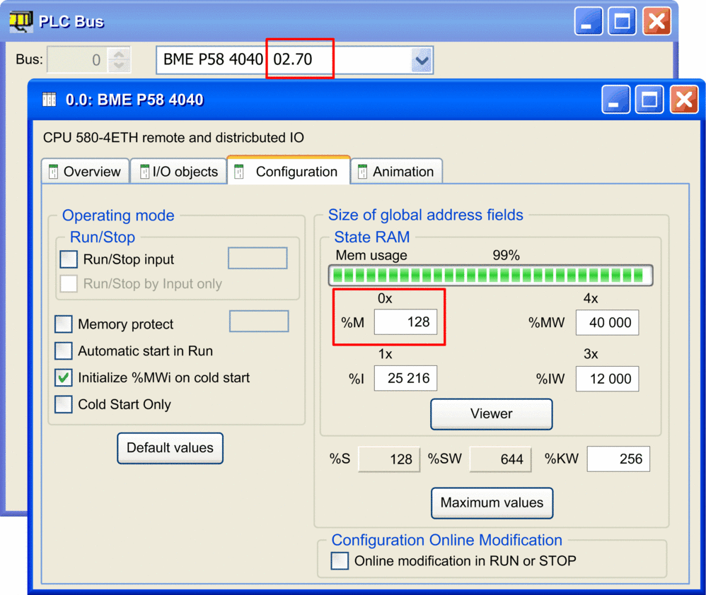
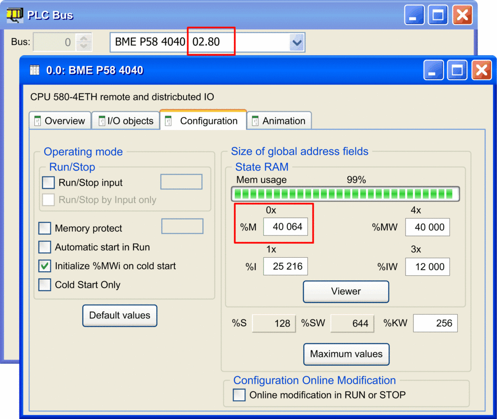
On M580 CPU SV 2.70 (or earlier), each %I and %M objects takes around 1 byte.
On M580 CPU SV 2.80 (or later) the space taken by each %I or %M is optimized and the state RAM can now be filled with a larger number of objects.
When Quantum Ethernet Remote drops are configured on M580 CPU SV 2.80 (or later), the total size of the state RAM is unchanged (128 Kbytes), but you can assign a larger number of %M and %I.
Example: with numbers of %IW = 12 000, %MW = 40 000, and %I = 25216, the maximum number of %M is 128 on CPU SV 2.70 while it is 40 064 on CPU SV 2.80.


Completing the Ethernet Network Configuration
After you configure these settings, configure the CPU settings beginning with its Channel Properties. Then configure the Ethernet network devices.


 toolbar button) to save
the configuration.