Introduction
You can install any standard CPU (BMEP58•0•0) or any Hot Standby CPU (BMEH58•0•0) in these racks:
BMXXBP•••• (PV:02 or later) X Bus rack
BMEXBP••00 or BMEXBP••02 Ethernet rack
Exception: You can install the BMXCPS4002 only on these dual-bus (Ethernet and X Bus) racks:
BMEXBP0602
BMEXBP1002
Installation Precautions
An M580 CPU is powered by the rack bus. Confirm that the rack power supply is turned off before installing the CPU.
| DANGER | |
|---|---|
Remove the protective cover from the rack slot connectors before plugging the module in the rack.
| WARNING | |
|---|---|
%SW97 to check the status
of the SD card.Grounding Considerations
Follow all local and national safety codes and standards.
| DANGER | |
|---|---|
Installing the CPU
Install the CPU in the rack slots marked 00 and 01. If you do not install the CPU in these two slots, it starts in NOCONF state state and uses the default IP address, which starts with 10.10 and uses the last two bytes of the MAC address.
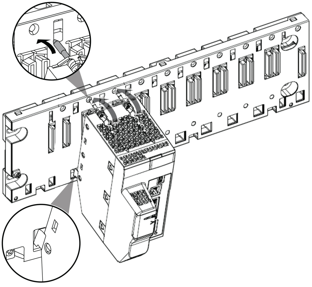
Follow these steps to install a CPU in a rack:
Step |
Action |
Illustration |
|---|---|---|
1 |
Verify that the power supply is turned off. |
– |
2 |
If you are installing a Hot Standby CPU, on the back of the CPU, set the A/B/Clear selector switch to the appropriate selection, “A” or “B”. NOTE: When you later install the companion Hot Standby
CPU, set its rotary switch to the other A/B position.
|
– |
3 |
Verify that:
|
 |
4 |
Position the locating pins situated at the rear of the module (on the bottom part) in the corresponding slots in the rack. |
|
5 |
Swivel the module towards the top of the rack so that the module sits flush with the back of the rack. The module is now set in position. |
|
6 |
Tighten the 2 screws on top of the CPU to maintain the module in place on the rack. tightening torque: 0.7...1.5 N•m (0.52...1.10 lbf-ft). |
– |
Installing Modules in the Second Local Rack
If you are installing a Hot Standby system, you need to install the same collection of modules, with the same versions of firmware, that were installed on the first rack. Install each module in the same slot that its counterpart occupies on the first rack. Follow the same procedure described above, except set the A/B/Clear selector switch on the back of the standby CPU to other A/B position.
Connecting the Hot Standby Local Racks
If you are installing a Hot Standby system, you need to connect the communication link to CPU A and CPU B before applying power to either local rack. If you start up the CPUs before they are connected via the Hot Standby link, both CPUs attempt to assume the role of primary CPU in your Hot Standby system.
| DANGER | |
|---|---|
| DANGER | |
|---|---|
Before you connect the two Hot Standby local racks, verify that an equipotential grounding system is in place that includes the two racks (plus any other equipment you intend to connect to the two Hot Standby local racks).
| NOTICE | |
|---|---|
Each Hot Standby CPU includes on its front face an SFP socket. This socket can accept an SFP transceiver module for either copper or single mode fiber optic cabling of the Hot Standby link. Your choice of SFP transceiver and cabling is determined by the distance between the two Hot Standby local racks.


