

PAC Hot Standby CPU Modules
These M580 CPU modules support M580 Hot Standby systems:
BMEH582040, BMEH582040C, BMEH582040S
BMEH584040, BMEH584040C, BMEH584040S
BMEH586040,BMEH586040C, BMEH586040S
CPU Module Front and Back Views
The three Hot Standby CPU modules have the same external hardware features. The front of the module is on the left. The back of the module is on the right:
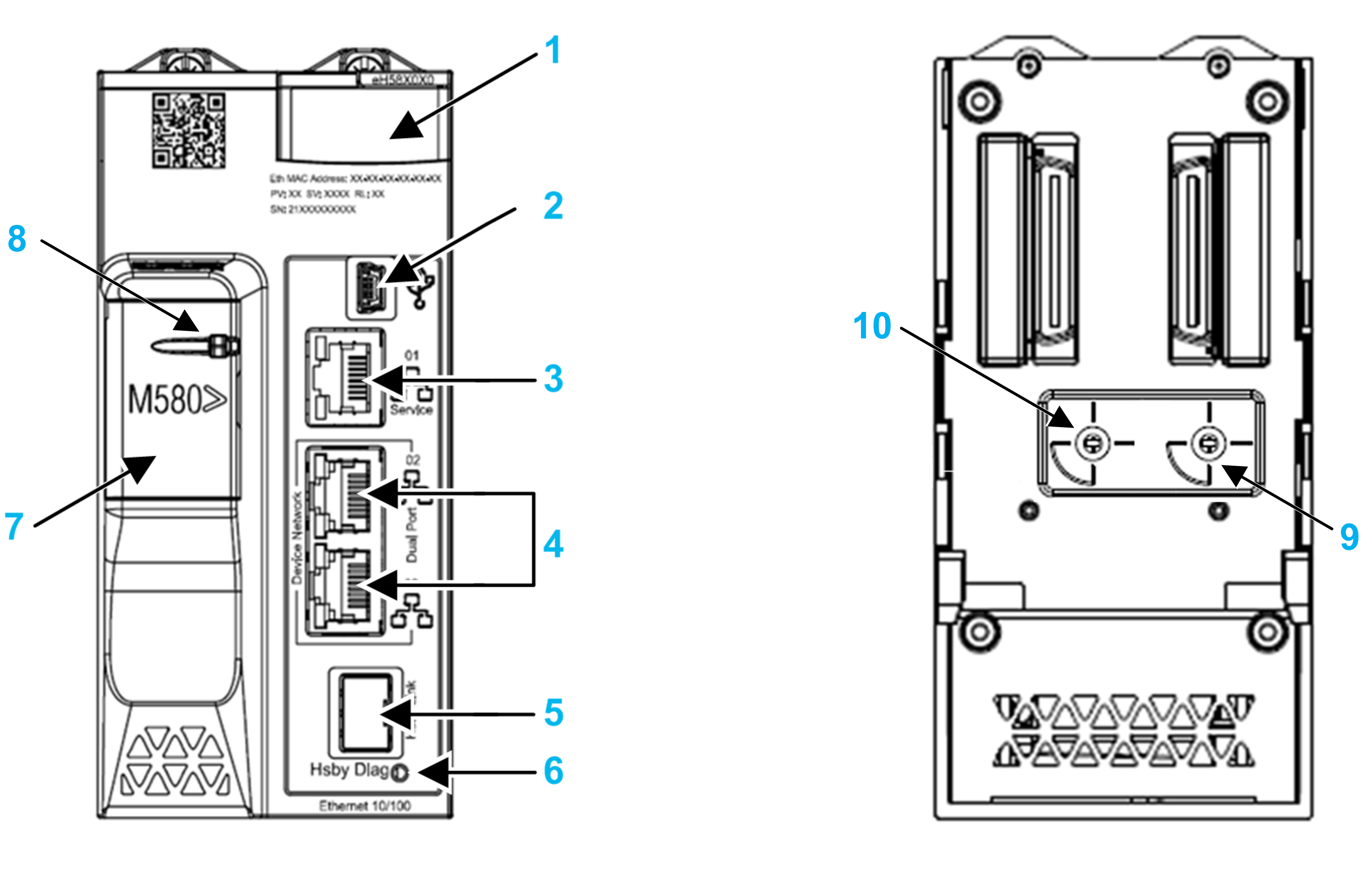
1 LED diagnostic display panel
2 Mini-B USB port for module configuration via PC running Control Expert
3 RJ45 Ethernet service port connector
4 RJ45 connectors that together serve as a dual port to the Ethernet network
5 SFP socket for copper or fiber-optic Hot Standby link connection
6 Hot Standby status link LED
7 SD memory card slot (behind door)
8 SD memory card lockable door
10 Hot Standby rotary selector, used to designate the PAC as either PAC A or PAC B, or to Clear the existing Control Expert application
Hot Standby Rotary Selector Switch
Use the rotary switch on the back of each M580 Hot Standby CPU to designate the role that the CPU plays in the M580 Hot Standby configuration:
Use only the small, plastic screwdriver provided with the CPU to set the rotary switch according to its role in a Hot Standby system.
| NOTICE | |
|---|---|
Rotary switch settings include:
Position |
Result |
|---|---|
A |
|
B |
|
Clear |
NOTE: Setting the switch for each Hot Standby PAC to the same A/B position can cause a a conflict of PAC
roles.
|
Clearing CPU Memory
To clear a CPU memory, follow these steps:
Step |
Action |
|---|---|
1 |
Set the rotary switch to Clear. |
2 |
Power up the PAC. |
3 |
Power down the PAC. |
4 |
Set the rotary switch to A or B. |
When you next power up the PAC, if the remote PAC is primary, the primary PAC transfers the application to the local PAC.
SFP Socket
Each CPU module includes one SFP socket, to which you can connect either a fiber optic or a copper transceiver:
To insert a transceiver:
Step |
Action |
|---|---|
1 |
Check that the CPU is powered off. |
2 |
Position the transceiver so that its label is oriented to the left. |
3 |
Press the SFP transceiver firmly into the socket until you feel it snap into place. NOTE: If the SFP transceiver resists, check the orientation of the transceiver
and repeat these steps.
|
To remove a transceiver:
Step |
Action |
|---|---|
1 |
Check that the CPU is powered off. |
2 |
Pull out the latch to unlock the transceiver. |
3 |
Pull on the transceiver to remove it. |
| NOTICE | |
|---|---|
Each module comes with a stopper. When the SFP socket is not connected to a transceiver, cover the unused socket with the cover to keep out dust
Grounding Considerations
Follow all local and national safety codes and standards.
| DANGER | |
|---|---|