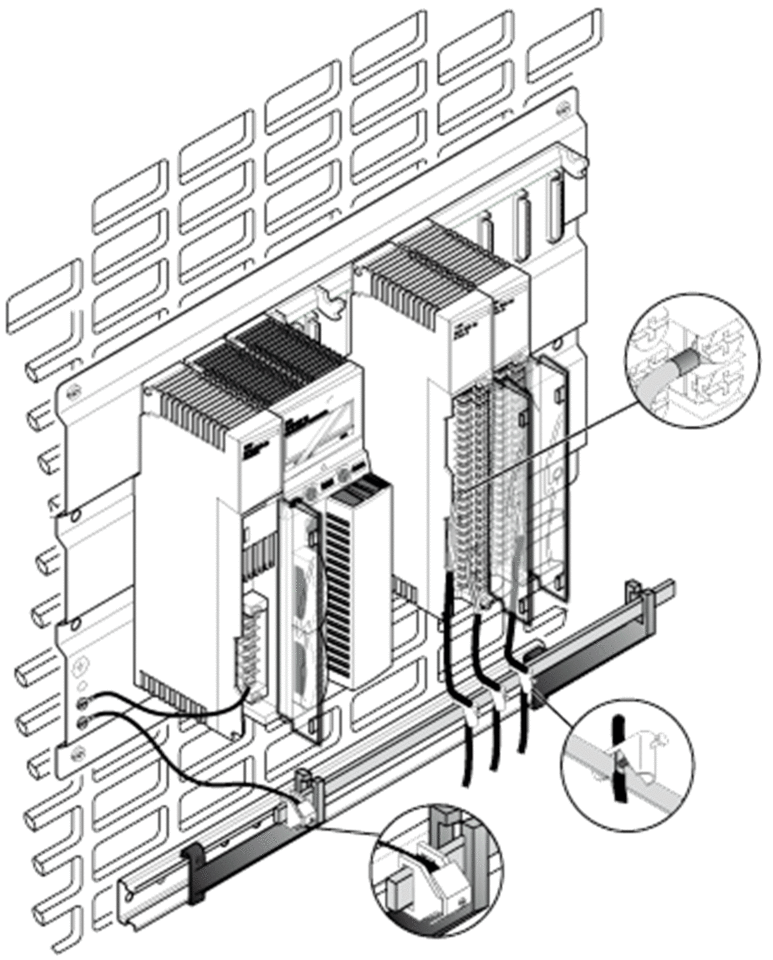
Overview
For the Analog Input Modules, the earthing must be done by the analog wires. Analog wires must be grounded directly when entering the cabinet. You may use an analog cable grounding rail. This section describes this approach.
Principle
High frequency interference can only be discharged via large surfaces and short cable lengths.
Guidelines
Follow these wiring guidelines:
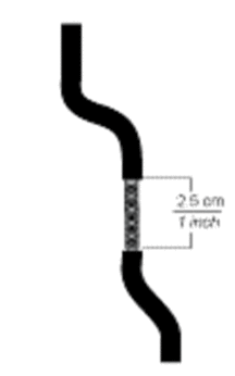
Use shielded, twisted-pair cabling.
- Expose 2.5 cm (1 inch) as shown:
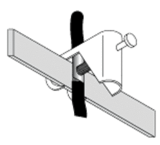
- Make sure the wire is properly grounded (connection between the grounding bar and the clamps).
Assembly of the STB XSP 3000 Kit
The followed kit is used to have a high quality of the analog signal.
The following table describes the STB XSP 3000 grounding kit.
Elements |
Description |
|---|---|
Side Supports and grounding bar |
The following illustration describes the assembly of the side supports and the grounding bar. 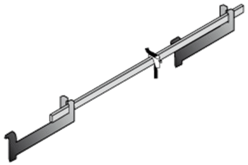 |
The following table describes the step to assemble the STB XSP 3000 grounding kit:
Step |
Description |
|---|---|
1 |
Push the side supports against the walls and tighten the screws. 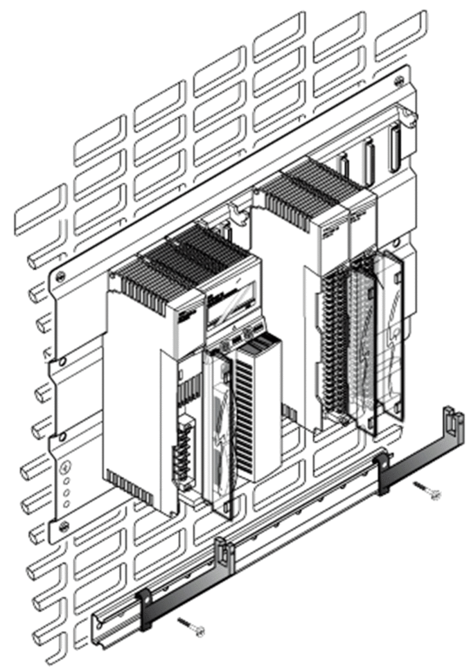 |
2 |
Choose the length of the grounding bar. 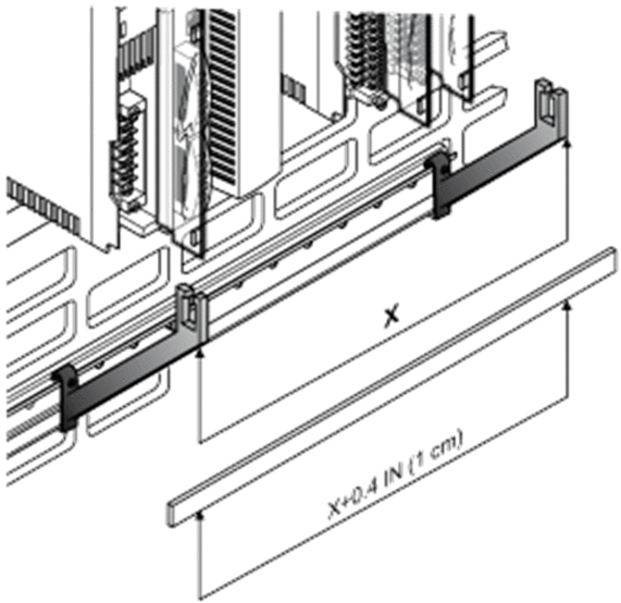 |
3 |
Insert the functional grounding terminal block and tighten the screw  |
4 |
Fix the grounding bar at the side supports. 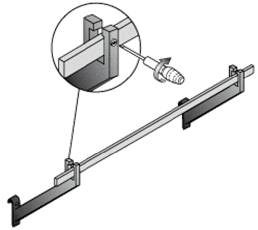 |
5 |
The following figure describes the final assembly of the STB XSP 3000. 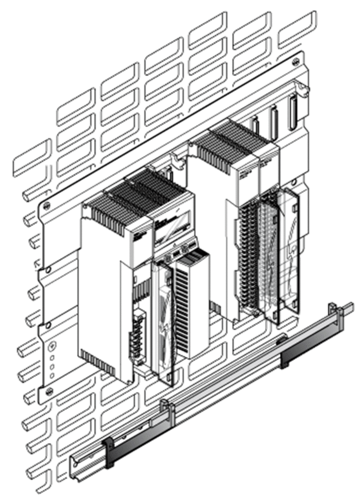 |
STB XSP 3010 Kit and STB XSP 3020
The following table describes the different cable sections (in AWG and mm2):
Reference |
AWG |
mm2 |
|---|---|---|
STB XSP 3010 |
16 to 9 |
1.5 to 6.5 |
STB XSP 3020 |
10 to 7 |
5 to 11 |
Final Assembly
The following figure shows the final assembly:
