At a Glance
The Discrete I/Os feature protective measures which ensure a high resistance to industrial environmental conditions. Certain rules, shown below, must nevertheless be respected.
External power supplies for sensors and pre-actuators
External sensor and pre-actuator power supplies associated with Discrete I/O modules must be protected against this short circuits and overloads by quick-blow fuses.
For HE10 connector Discrete I/O modules, the sensor/pre-actuator power supply must be linked to each connector, except in the event where the corresponding channels are not in use and are not assigned to any task.
In the event that the 24 VDC installation is not carried out according to SELV (safety extra low voltage) standards, the 24 VDC power supplies must have the 0V linked to mechanical ground, which is in turn linked to the ground as close as possible to the power supply. This restriction is necessary for personnel safety in the event of a power phase coming into contact with the 24 VDC supply.
Inputs
Recommendations for use concerning Discrete I/O module inputs are as follows:
for fast input modules (TSX DEY 16 FK/DMY 28FK/DMY 28RFK):
in the event that 24 VDC direct current inputs are used, it is recommended to adapt the filtering time to the required function;
in order for bounces not to be taken into account upon closure of contacts, it is not advisable to use sensors with mechanical contact outputs if the filtering time is reduced to under 3 ms;
for faster operation, the use of direct current inputs and sensors is recommended, as alternating current inputs have a much higher response time.
for 24 VDC inputs and line coupling with an alternating current network:
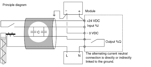
- operation can be disturbed if the coupling between cables relaying an alternating current and cables relaying signals intended for direct current inputs is too large. This is illustrated in the following circuit diagram.When the input contact is open, an alternating current exceeding the cable's interference capacities may generate a current in the input which might cause it to be set to 1.

the line capacity values that must not be exceeded, for a 240 VCA/50 Hz line coupling, are given in the summary table at the end of this paragraph. For a coupling with a different voltage, the following formula can be applied:
Acceptable capacity = (Capacity at 240 VAC x 240) / line voltage
for 24 to 240 VAC inputs and line coupling:
- In this case, when the line that controls the input is open, the current passes according to the coupling capacity of the cable (see circuit diagram below).

the line capacity values that must not be exceeded are given in the summary table at the end of this paragraph.
The summary table below shows the acceptable line capacity values.
Module |
Maximum coupling capacity |
|---|---|
24 VDC inputs |
|
TSX DEY 32 / TSX DEY 64D2K |
25 nF (1) |
TSX DEY 16D2 |
45 nF (1) |
TSX DEY 16FK / TSX DMY 28FK / TSX DMY 28RFK |
10 nF (1) (2) 30 nF (1) (3) 60 nF (1) (4) |
24 to 240 VAC inputs |
|
TSX DEY 16A2 |
50 nF |
TSX DEY 16A3 |
60 nF |
TSX DEY 16A4 |
70 nF |
TSX DEY 16A5 |
85 nF |
Legend |
|
(1) |
Max. admissible coupling capacity with 240 VAC / 50 Hz line |
(2) |
Filtering = 0.1 ms |
(3) |
Filtering = 3.5 ms |
(4) |
Filtering = 7.5 ms |
Outputs
Recommendations for use concerning Discrete I/O module outputs are as follows:
it is recommended to segment starts, protecting each one with a quick-blow fuse, if currents are high;
wires of a sufficient diameter should be used to avoid drops in voltage and overheating.
Cable routing
Precautions for use to be taken concerning the wiring system are as follows:
in order to reduce the number of alternating couplings, power circuit cables (power supplies, power switches, etc.) must be separated from input cables (sensors) and output cables (pre-actuators) both inside and outside the equipment.
outside the equipment, cables leading to inputs / outputs should be placed in covers that make them easily distinguishable from those containing wires relaying high energy levels. They should also be placed preferably in separate grounded metal cableways. These various cables must be routed at least 100 mm apart.


