Connecting or disconnecting the TELEFAST
You should always connect or disconnect the TELEFAST’s connectors and various connection wires when the voltage is SWITCHED OFF:
connecting or disconnecting the cable connectors linking the module and the TELEFAST connector,
connecting or disconnecting the wires linking the TELEFAST connector to the encoder.
Length of the connection cable between the module and the TELEFAST
The table below gives the clock frequency of the transmission series according to the distance.
If |
then |
|---|---|
cable length < to 10 meters |
frequency of the transmission series clock: 1 MHz |
cable length < to 20 meters |
frequency of the transmission series clock: 750 kHz |
cable length < to 50 meters |
frequency of the transmission series clock: 500 kHz |
cable length < to 100 meters |
frequency of the transmission series clock: 375 kHz |
cable length < to 150 meters |
frequency of the transmission series clock: 200 kHz |
cable length < to 200 meters |
frequency of the transmission series clock: 150 kHz |
Cross-section of the wire connecting the module and the TELEFAST
In order to reduce the on-line voltage falls as much as possible, please respect the following points:
If |
And |
Then |
|---|---|---|
The encoder is using a 5 VDC supply |
The distance from the module to the TELEFAST is < 100m |
Use a wire with minimum cross-section 0.08 mm (gage 28) |
The distance from the module to the TELEFAST is > 100m |
Use a wire with minimum cross-section 0.34 mm (gage 22) |
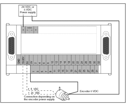
Connecting the encoder supply
In order to limit voltage falls with a 0V, caused by the encoder supply current, we recommend that you wire the 0V as follows:

Wiring the encoder outputs on the TELEFAST
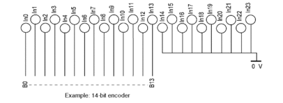
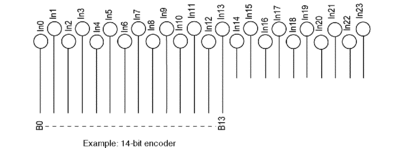
If the encoder outputs have positive or negative logic with a number lower than 24, use the following connection procedure:
If |
And |
Then |
|---|---|---|
the encoder outputs have positive logic |
their number is lower than 24 |
|
 |
||
the encoder outputs have negative Logic |
their number is lower than 24 |
|
 |
||
Protecting the encoder supply
According to the encoder supply voltage, the supply should be protected as follows:
If |
Then |
|---|---|
The encoder supply voltage is 10…30 VDC |
The protective fuse is built into the TELEFAST:
|
The encoder supply voltage is 5 VDC |
Provide a series fuse (Fu) for the positive supply:
|
Monitoring the encoder supply
If the encoder supply voltage decreases by more than 15%, the default (EPSR signal) is sent back to the module. If the encoder does not have a return supply, do the following:
If |
Then |
|---|---|
No return encoder supply |
Connect the positive and negative EPSR of the TELEFAST:
|


