Introduction
The encoder supply can be connected:
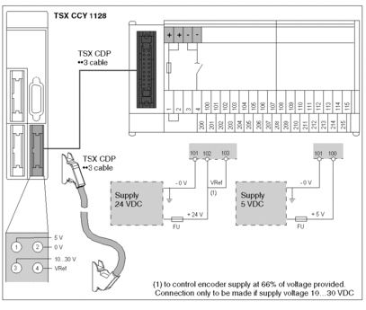
either by using a TELEFAST ABE-7H16R20 cable interface, which is then connected to the module using a TSX CDP ••3 cable.
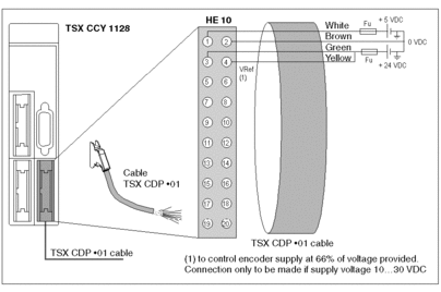
or directly, using a TSX CDP •01 pre-wired strand
Process diagram for connecting the encoder supply to the TELEFAST interface
The diagram below shows the process for connecting the encoder supply.
At 24 VDC for an encoder with a 10…30 VDC supply format,
and at 5 VDC for an encoder with a 5 VDC supply.

Catalog of TSX CDP ••3 connector cables
The table below gives the different references for the cables connecting the TELEFAST to the module, and their respective lengths.
Cable references |
Cable lengths |
|---|---|
TSX CDP 053 |
0.5 meters |
TSX CDP 103 |
1 meter |
TSX CDP 203 |
2 meters |
TSX CDP 303 |
3 meters |
TSX CDP 503 |
5 meters |
Diagram showing the process for connecting the supply using a TSX CDP •01 pre-wired strand
The diagram below shows the process for connecting the encoder supply.
At 24 VDC for an encoder with a 10…30 VDC supply format,
and at 5 VDC for an encoder with a 5 VDC supply.

Catalog of TSX CDP •01 connector cables
The table below gives the different references for the cables connecting the TELEFAST to the module, and their respective lengths.
Cable references |
Cable lengths |
|---|---|
TSX CDP 301 |
3 meters |
TSX CDP 501 |
5 meters |
Recommendations
Maximum length of wires between the supply outputs and the connection points on the TELEFAST: must be less than 0.5 meters.
Protection on the + supply: although the module has several built-in protection systems to guard against wiring errors and accidental short-circuits on the cables, it is vital to install a 1A maximum non-delay fuse (Fu) on the + supply.
Connection of the 0 V supply to the protective ground: must be as close as possible to the supply output.


