Responding to Errors
Original instructions
Overview
The following information describes how to respond to errors on the NOE module.
Detecting Errors
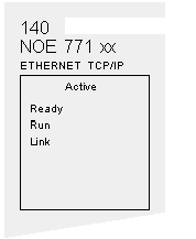
When faults occur, the NOE module’s LED display can help you determine what went wrong. The following figure shows the pattern that the LEDs should display during normal operation.
The Run indicator will be solid. The Coll (collision) LED may flash, indicating that collisions are occurring on the Ethernet network. Such collisions are normal.
If a fault occurs, the normal LEDs may be extinguished or other indicators may light. This topic discusses errors reported by the Active, Ready, Coll, Link, Kernel, Appl and Fault indicators.
For each type of error, try the suggested remedies in the order given. If no remedy suggested here overcomes the error, call your local service representative or call Schneider Electric customer service at 1-800-468-5342 for further directions.
Procedure for Responding to an Active LED Error Indicator
If the Active LED fails to light, the NOE module is not communicating with the backplane . The following procedure describes the steps to perform to respond to an Active LED error.
Step
Action
1
Make sure the NOE module and the controller are installed properly.
2
Verify that the controller is working; if it is not, replace it.
3
If neither the new controller nor the NOE module functions, replace the backplane.
4
Make sure that the number of network option modules (including NOE, NWM, NOM, and CRP 811 modules) in the backplane is not exceeded:
  • 140 CPU 311 10: 2 modules
  • 140 CPU 670 60: 3 modules
  • 140 CPU 434 12A, 140 CPU 534 14A, 140 CPU 651 x0, 40 CPU 652 60, 140 CPU 658 60, 140 CPU 671 60, 140 CPU 672 60, 140 CPU 672 61, 140 CPU 678 61: 6 modules
5
Check the version of the controller executive. You must have version 2.0 or later to support the Ethernet module. Earlier versions do not recognize the module.
6
If steps 4 and 5 above check out ok, replace the NOE module.
Procedure for Responding to a Ready LED Error Indicator
If the Ready LED fails to light, the NOE module has failed internal diagnostic tests. The following procedure describes the steps to perform.
Step
Action
1
Make sure that power has been applied to the backplane.
2
If step 1 checks out ok, replace the NOE module.
Procedure for Responding to a Link LED Error Indicator
If the Link LED fails to light, the NOE module is not communicating with the Ethernet hub/switch. The following procedure describes the steps to perform to respond to a Link LED error.
Step
Action
1
Make sure that the cable has been installed correctly and the module is functioning properly.
2
Verify that the hub/switch is working properly.
3
If steps 1 and 2 check ok, replace the NOE module.
Kernel LED Error
The following table describes the Kernel LED errors that may occur and how to respond to them.
If
Then
The Ready LED is on and the Kernel LED is flashing
The module has detected an invalid software image.
The Ready LED is on and the Kernel LED is shining steadily,
An attempt to download a software image has failed and the module is in kernel mode.
Either of the above conditions exists.
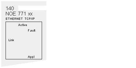
Fault LED
The Fault LED will flash briefly following an error as the module attempts to recover.
The following figure shows the Fault LED.
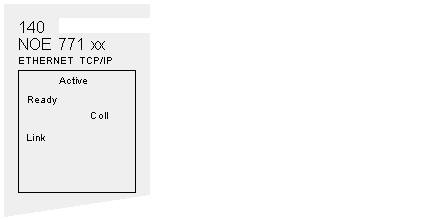
Collision LED Error
If the twisted pair cable has not been connected properly, the Coll LED will shine steadily and the Link LED will be extinguished. (This condition does not occur with fiber optic modules.)
The following figure shows the Collision LED.
Procedure for Responding to a Collision LED Error
If the Collision LED fails to light, use the following procedure.
Step
Action
1
Make sure that the cable has been installed and is working properly.
2
Verify that the Ethernet Hub/Switch is working properly.
Collision LED Normal Condition
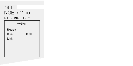
If the Coll LED is flashing, the module is reporting collisions on the Ethernet network. While such collisions are normal, the frequency of the flashes is an indication of the volume of traffic on the network. The flashes may be so frequent that the LED appears to be shining steadily. Heavy traffic will slow communications. If response time is important to your application, you should consider segmenting your network to reduce the frequency of collisions.
The following figure shows the Collision LED under normal conditions.
Run LED
The following table describes the action to be taken if the Run LED is flashing. The action depends on the number of flashes in sequence.
Number of Flashes in Sequence
Action
Three
Check Ethernet connection
Four
Change IP address
Five
Provide IP address
Six
Connect using default IP address and configure
Seven
Application LED
If the module crashes, it will note the reason in a log. If the module is able to recover, the Appl LED will light, indicating that an entry has been made in the crash log. You can read and clear the crash log.