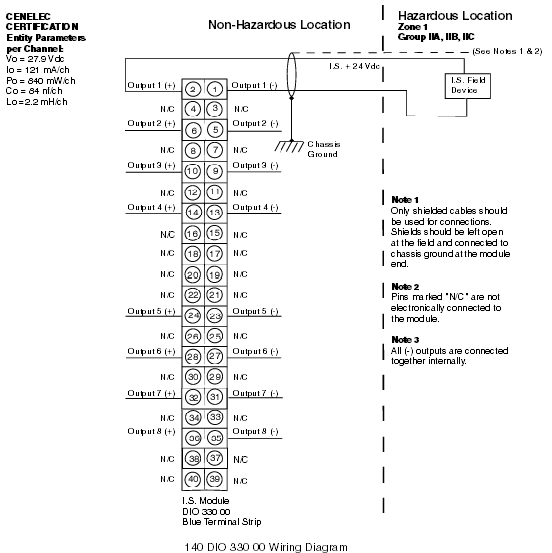
Celenec Approved Wiring Diagram
The following is a Celenec certified wiring diagram for this module.
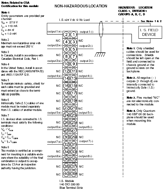
CSA Approved Wiring Diagram
The following is a CSA certified wiring diagram for this module.
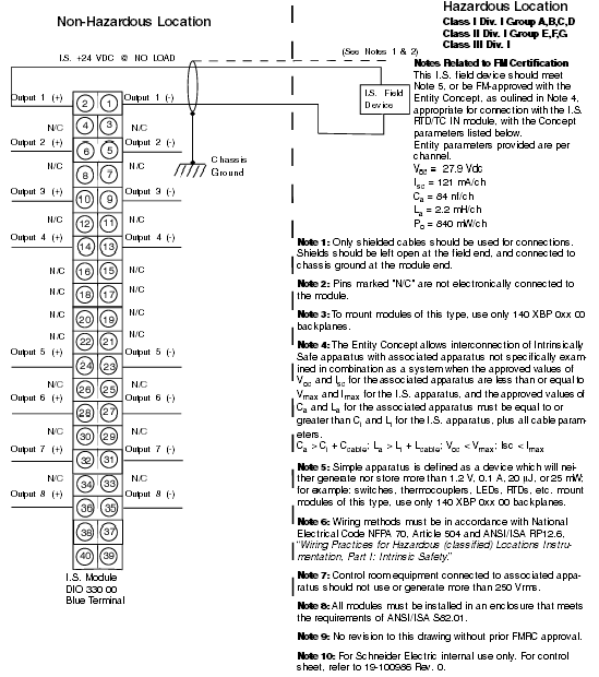
FM Approved Wiring Diagram
The following is a FM certified wiring diagram for this module.
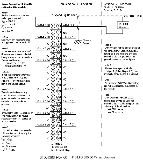
UL Approved Wiring Diagram
The following is a UL certified wiring diagram for this module.
The Quantum 140 DIO 330 00 Intrinsically Safe Digital Output module is designed with a fixed wiring system where the field connections are made to a 40-pin, fixed position, blue terminal strip, which is plugged into the module.
Field wiring to the module consists of separate shielded, twisted pair wires. Acceptable field wire gauges go from AWG 20 to AWG 12. Wiring between the module and the intrinsically safe field device should follow intrinsically safe wiring practices, to avoid the transfer of unsafe levels of energy to the hazardous area.
NOTE: The tightening torque must be between 0.5 Nm and 0.8 Nm.
Terminal Strip Color and Keying Assignment
The module’s 140 XTS 332 00 field wiring terminal strip is color-coded blue to identify it as an intrinsically safe connector.
The terminal strip is keyed to prevent the wrong connector from being applied to the module. The keying assignment is given below.
|
Module Class
|
Module Part Number
|
Module Coding
|
Terminal Strip Coding
|
|
Intrinsically Safe
|
140 DIO 330 00
|
CDE
|
ABF
|


