Wiring Diagram
Original instructions
Illustration
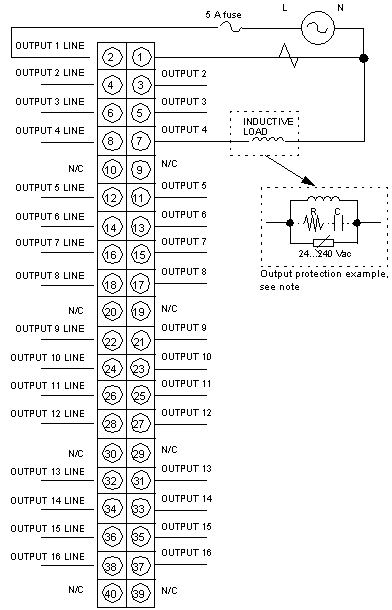
The following figure shows the 140 DAO 840 00 wiring diagram.
1. 
This module is not polarity sensitive.
2. 
N / C = Not Connected.
3. 
Voltages up to 133V may be different phases on adjacent output points.
4. 
Voltages over 133V of different phases must have an output point separation between them. For example: Output 1 and 2 - Phase A, Skip Output 3, Output 4 - Phase B.
5. 
When field wiring the I/O module, the maximum wire size that should be used is 1-14 AWG or 2-16 AWG; the minimum size is 20 AWG.
NOTE: The tightening torque must be between 0.5 Nm and 0.8 Nm.
NOTICE
DESTRUCTION OF ADAPTER
  • Before tightening the locknut to the torque 0.50...0.80 Nm, be sure to properly position the right-angle F adapter connector.
  • During tightening, be sure to maintain the connector securely.
  • Do not tighten the right-angle F adapter beyond the specified torque.
Failure to follow these instructions can result in equipment damage.
DANGER
HAZARD OF ELECTRIC SHOCK, EXPLOSION OR ARC FLASH
Before accessing the fuses,
  • Remove the power to the module (pre-actuators), and
  • disconnect the terminal block.
  • Always use a properly rated voltage sensing device at all line and load fuse clips to confirm power is off.
Failure to follow these instructions will result in death or serious injury.
CAUTION
EQUIPMENT DAMAGE
Protect each output point with an external fuse. Schneider Electric recommends a 5 A fuse with an I2T rating of less than 87.
Failure to follow these instructions can result in injury or equipment damage.
CAUTION
DAMAGE TO MODULE OUTPUTS
  • Ensure that the AC power energizing each group is from a common, single-phase AC power source.
  • Protect the module output when an external switch is used to control an inductive load in parallel with the module output. Use an external varistor (Harris V390ZA05 or equivalent) in parallel with the switch.
Failure to follow these instructions can result in injury or equipment damage.
NOTE:
The output protection is composed of an RC filter (snubber filter) and a varistor:
  • The snubber filter is optional. The values of R and C are not provided as they depend on the device used.
  • Choose the varistor with appropriate electronic characteristics depending on the voltage required by the device used.