|
Specifications
|
|
|
Original instructions
|
|
Module Type
|
12 OUT (2 groups x 6 points)
|
|
External Power
|
None
|
|
Power Dissipation
|
1.0 W + 0.77 W x points ON
|
|
Bus Current required
|
6 points ON: 375 mA
12 points ON: 650 mA
|
|
I/O map
|
1 input word
1 output word
|
|
Fault Detection
|
Over Current (see note below)
|
|
Operating Voltage (max.)
|
19.2 ... 156.2 VDC including ripple
|
|
ON State Drop / Point
|
0.75 VDC @ 0.5 A
|
|
Each Point
|
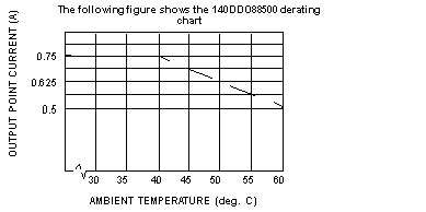
0.75 A < 40 degrees C (see the operating curve)
|
|
Each Group
|
3 A, 0 ... 60 degrees C
|
|
Per Module
|
6 A, 0 ... 60 degrees C
|
|
Surge Current (max.)
|
4 A @1 ms duration (no more than 6 per minute)
|
|
Peak Load Current
|
4 A for T ≤ 1 ms
|
|
OFF State Leakage / Point
|
0.5 mA @ 150 VDC
|

|
@ 130 VDC
|
46 W per point
|
|
@ 115 VDC
|
41 W per point
|
|
@ 24 VDC
|
8 W per point
|
|
Inductance
|
Internal Diode protected, no limit on Inductance
|
|
Switching Frequency
|
50 Hz (max.)
|
|
Field to Bus
|
2500 VAC rms for 1 minute
|
|
Group to Group
|
1200 VAC rms for 1 minute
|
|
Output Protection (internal)
|
Group varistor and individual point over Current sense
|
|
OFF - ON
|
1 ms
|
|
ON - OFF
|
1 ms
|