Wiring Diagram
Original instructions
Illustration
CAUTION
UNWIRED INPUTS CAUSE INVALID READINGS
When configured for voltage inputs (no jumper installed between In(+) and sense terminals), if a broken field wire occurs, readings will be non-zero and not predictable.
Failure to follow these instructions can result in injury or equipment damage.
The following figure shows the wiring diagram for the 140 AMM 090 00 analog input/output module.
External Wiring Recommendation
The following information pertains to the wiring diagram above.
Output Section 2 Channels
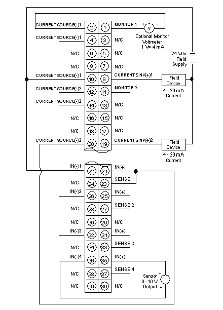
Typical Wiring Outputs
Channel 1
The output shows a connection to an external field device and optional monitor.
Channel 2
The output shows a connection to an external field device and the input of channel 1.
Input Section 4 Channels
Typical Wiring Inputs
Channel 1
Channel 1 shows 4 - 20 mA current input controlled by output section Channel 2.
Channel 4
The input shows a connection to a voltage output sensor.
  1. Jumpers are required between IN (+) and SENSE terminals for all current input ranges.
  2. Pins 1 ... 20 are outputs.
    Pins 21 ... 40 are inputs.
  3. Use shielded signal cable. In noisy environnements, twisted shielded cable is recommended.
  4. Shielded cables should be connected to the PLC’s ground.
  5. A Shield Bar (STB XSP 3000 and STB XSP 3010/3020) should be used to connect the shielded cable to ground.
  6. For Inputs, the maximum channel to channel working voltage cannot exceed 30 Vdc.
  7. N / C = Not Connected.
NOTE: V is an optional voltmeter that can connected to read voltage that is proportional to the current. Wiring to this terminal must not exceed 1 m.
NOTE: When field wiring the I/O module, the maximum wire size that should be used is 1-14 AWG or 2-16 AWG; the minimum size is 20 AWG.
NOTE: The tightening torque must be between 0.5 Nm and 0.8 Nm.
NOTICE
DESTRUCTION OF ADAPTER
  • Before tightening the locknut to the torque 0.50...0.80 Nm, be sure to properly position the right-angle F adapter connector.
  • During tightening, be sure to maintain the connector securely.
  • Do not tighten the right-angle F adapter beyond the specified torque.
Failure to follow these instructions can result in equipment damage.