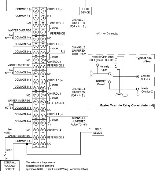
Wiring Diagram
Original instructions
Illustration
WARNING
UNINTENDED EQUIPMENT OPERATION
Before removing the connector, remove the field power or ensure that pre-actuator wiring can remain in an open circuit condition.
Failure to follow these instructions can result in death, serious injury, or equipment damage.
WARNING
UNINTENDED EQUIPMENT OPERATION
Avoid erroneous outputs in this module by connecting the master override to an external source through a 1/16 amp in-line fuse or connecting to circuit common.
Failure to follow these instructions can result in death, serious injury, or equipment damage.
The following figure shows the wiring diagram for the 140 AVO 020 00 module.
External Wiring Recommendation
  1. When the green channel status LEDs are off, the module is not generating outputs, however, an output may still be present if the master override signal is used.
  2. Master override is an input connected via an internal relay contact to the output when the module is not active. If connected to an external source, the master override input must be fused by a 1/16 A fuse.
  3. If the master override is not connected to an external source, then it must be connected to common of that channel.The master override relay transition time is typically 2 ms.
  4. The master override inputs must be from an external supply with a source impedance of <200Ω or tied to system common. These inputs for channels that are in use should not be allowed to float and may be unique for each.
NOTE: When field wiring the I/O module, the maximum wire size that should be used is 1-14 AWG or 2-16 AWG; the minimum size is 20 AWG.
NOTE: The output levels of this module are either those generated within the module based on data inputs from the system, or from the master override inputs on the field-wiring terminal strip.
NOTE: The tightening torque must be between 0.5 Nm and 0.8 Nm.
NOTICE
DESTRUCTION OF ADAPTER
  • Before tightening the locknut to the torque 0.50...0.80 Nm, be sure to properly position the right-angle F adapter connector.
  • During tightening, be sure to maintain the connector securely.
  • Do not tighten the right-angle F adapter beyond the specified torque.
Failure to follow these instructions can result in equipment damage.