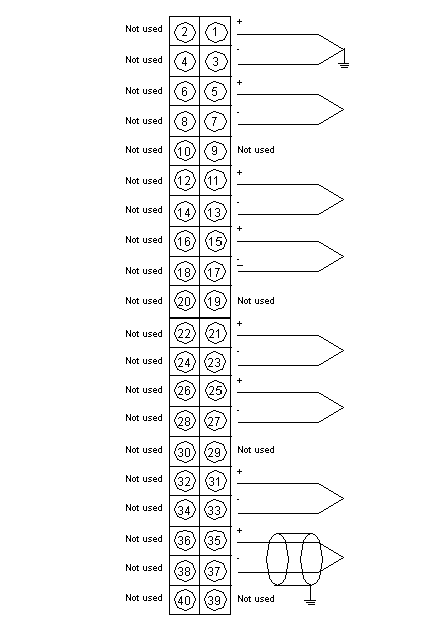
The following figure shows the wiring diagram of the 140 ATI 030 00.
External Wiring Recommendation
-
Use shielded TCs. (The user should consider using shielded wire in a noisy environment.)
-
Shielded types should be connected to the PLC’s ground.
-
-
Connections marked Not Used are not electrically connected within the module. These points are used as a thermal link to ambient air. They are not recommended as electrical tie points as this could affect the accuracy of cold junction compensation.
-
The 140 CFA 040 00 CableFast block can be used. However it can create a temperature variation up to 35.6 °F (2 °C). For more information, refer to the Modicon Quantum Automation Series Hardware Reference Guide (840 USE 100).
NOTE: When field wiring the I/O module, the maximum wire size that should be used is 1-14 AWG or 2-16 AWG; the minimum size is 20 AWG.
NOTE: The tightening torque must be between 0.5 Nm and 0.8 Nm.
Using Cold Junction Compensation (CJC)
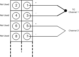
For temperature measurements, the 140 ATI 030 00 provides an internal CJC. However, a remote CJC can be used with the following TC types: J,K and T. The TC must be connected to Channel 1.
NOTE:
Recomendation when using remote CJC:
-
To obtain the best accuracy when using a remote CJC, connect it as close as possible from the 140 ATI 030 00 module.
-
The distance between the external CJC and the module affects the temperature measurement accuracy.
-
The usage of CableFast with a remote CJC is not recommended.
The following diagram shows how to connect a remote Cold Junction Compensation using a temperature compensation on the 140 ATI 030 00:
For more information on the 140 ATI 030 00 please refer to the Modicon Quantum Automation Series Hardware Reference Guide (840 USE 100).

