The following information describes how the data exchanged between the 140 SDO 953 00S module and the processor module are mapped.
Except for the health word, the data described here are transferred to and from the 140 SDO 953 00S module using the Quantum global backplane communication access mechanism which is common to all Quantum modules.
NOTE: The words "input" and "output" used here are defined with respect to the processor module.
11 words are necessary for this module:
-
4 words dedicated to output data
-
6 words dedicated to inputs data:
-
1 dedicated to energized/de-energized channel detection
-
1 dedicated to overload errors
-
1 dedicated to unsafe channel errors
-
1 dedicated to process power supply status, malfunction from the host (and exchange number which is used by the module)
-
2 words used by the module (CRC)
-
1 health word (this word is accessible by the processor module only)
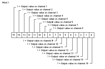
Flat Addressing (Output words)
The following diagram shows the register of the first output word. On bit 15, you read the output value of channel 1, on bit 14, you read the output value of channel 2, and so on.
Words 2, 3 and 4 are used by the module for internal checking:
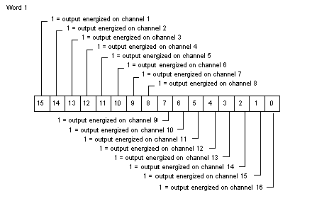
Flat Addressing (Input words)
The following diagram shows the register of the first input word. If bit 15 is set to 1, it means that the output is energized on channel 1. If bit 14 is set to 1, it means that the output is energized on channel 2, and so on.
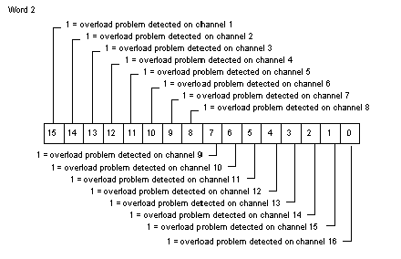
The following diagram shows the register of the second input word. Bit 15 set to 1 means that there is an overload problem on channel 1, bit 14 set to 1 means that there is an overload problem on channel 2, and so on.
NOTE: In case of activation of the overload bit, the corresponding output is automatically switched to the OFF state by the module (disjunction) and maintained OFF during at least 10 seconds. To recover the control of the output, it is necessary to set by application the overloaded output command of the module to the OFF state.
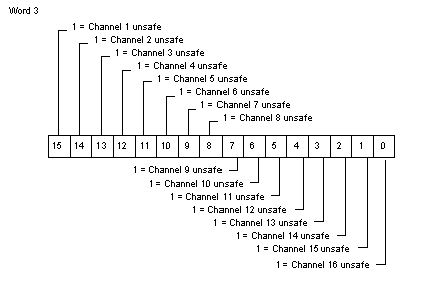
The following diagram shows the register of the third input word. If bit 15 is set to 1, it means that f the internal checks have detected a malfunction of channel 1, etc.
On word 4, bit 15 is dedicated to the Process Power supply Error. It is set to 1 if the external power supply is no longer detected.
On word 4, bit 14 is dedicated to the System Shut Down. It is set to 1 if the module has detected a malfunction from its host. In that case, the module is safe and shuts down.
The other bits on word 4 and words 5 and 6 are used by the module for internal checking:
The health word is an extra system control generated by the processor module, using the data read from the output module.
Any of these errors activates the health word:
-
overload problem (activates only the corresponding bit of the health word)
-
unsafe channel (activates only the corresponding bit of the health word)
-
malfunction of the host (SSD)
-
process power supply problem
-
CRC error
-
incorrect exchange number
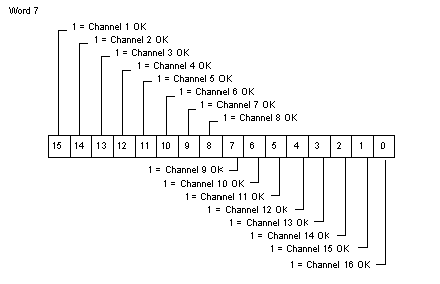
The following diagram shows the register of word 7.
Bit 15 to bit 0:
These 16 bits are set to 1 when no error is detected.