The following information describes how the data exchanged between the 140 SDI 953 00S module and the processor module are mapped.
Except for the health word, the data described here are transferred from the 140 SDI 953 00S module using the Quantum global backplane communication access mechanism which is common to all Quantum modules.
NOTE:
7 words are necessary for this module:
-
1 word dedicated to channel values
-
1 word dedicated to wiring problems
-
1 word dedicated to channel state (valid/invalid channel)
-
1 word dedicated to power supply status (and exchange number which is used by the module)
-
2 words used by the module (CRC)
-
1 health word (this word is accessible by the processor module only)
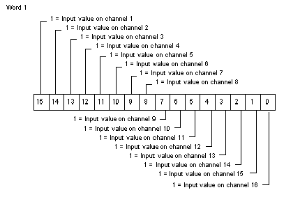
The following diagram shows the register of word 1. On bit 15, you read the input value of channel 1, on bit 14, you read the input value of channel 2, and so on.
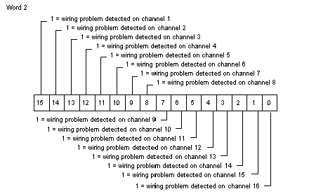
The following diagram shows the register of word 2. Bit 15 is set to 1 if no leakage current is detected on the sensor of channel 1, bit 14 for channel 2, and so on.
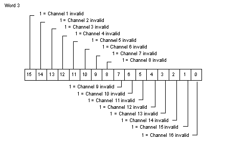
The following diagram shows the register of word 3. If bit 15 is set to 1, it means that channel 1 has detected an invalid channel, bit 14 is for channel 2, and so on.
On word 4, bit 15 is dedicated to the Process Power supply status. It is set to 1 if the external power supply is no longer detected.
The other bits on word 4 and words 5 and 6 are used by the module for internal checking:
The health word is an extra system control generated by the processor module, using the data read from the input module.
Any of these errors activates the health word:
-
broken wire (activates only the corresponding bit of the health word)
-
invalid channel (activates only the corresponding bit of the health word)
-
process power supply not detected
-
CRC error
-
incorrect exchange number
If an unhealthy input is detected (if a bit on word 7 is set to 0), the value of the corresponding channel is set to 0 (on word 1).
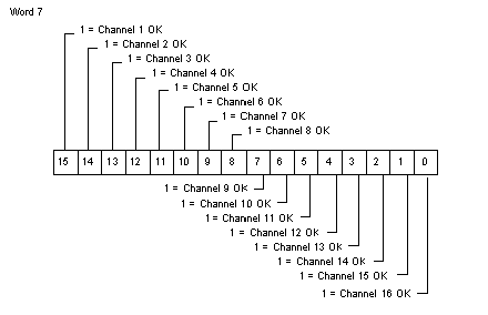
The following diagram shows the register of word 7.
Bit 15 to bit 0:
These 16 bits are set to 1 when no error is detected.