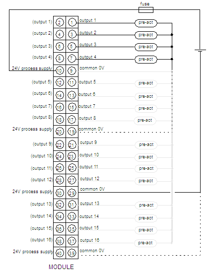
Wiring Diagram
Original instructions
Precautions
It is mandatory to use a process power supply which does not recover automatically after a disjunction. Use for instance 24 VDC 10 A ABL8 RPS24100 in manual mode.
CAUTION
OVERCURRENT TO THE OUTPUTS
Use fast acting fuses to protect the electronic components of the module from overcurrent. Improper fuse selection could result to damage to the module.
Failure to follow these instructions can result in injury or equipment damage.
Illustration
The following figure shows the wiring diagram for the 140 SDO 953 00S module.
power supply: 
24 VDC
fuse: 
10 A max (determined by the module load current), fast blow
pre-act: 
pre-actuator
NOTE: There is only one group of 16 outputs. All common 24 V are internally connected and all common 0V are also internally connected. For safety applications, it is recommended to connect at least 2 ground lines (common 0V) to the field wiring terminal block. The two pins of a same input (e. g: pin 1 and 2 for input 1) are internally connected too so that you can use either the right pin or the left one.
NOTE: The tightening torque must be between 0.5 Nm and 0.8 Nm.
NOTICE
DESTRUCTION OF ADAPTER
  • Before tightening the locknut to the torque 0.50...0.80 Nm, be sure to properly position the right-angle F adapter connector.
  • During tightening, be sure to maintain the connector securely.
  • Do not tighten the right-angle F adapter beyond the specified torque.
Failure to follow these instructions can result in equipment damage.