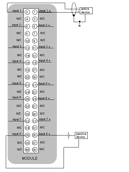
Connect each end of the cable shields, as follows:
on the sensors side: connect to the shield continuation terminals (ground terminals),
on the module side: clamp the shielding to the ground using grounding equipment STB XSP 3000 grounding kit and grounding clips (STB XSP 3010 or STB XSP 3020).
Field wiring:
Field wiring to the module consists of separate shielded twisted pair wires.
Illustration
The following figure shows the wiring diagram for the 140 SAI 940 00S module.
N/C:
No Connection
internal input impedance:
287 ohms
Rmin (of the passive device):
913 ohms
Rmax (of the passive device):
7713 ohms
NOTE: The tightening torque must be between 0.5 Nm and 0.8 Nm.
NOTICE
DESTRUCTION OF ADAPTER
Before tightening the locknut to the torque 0.50...0.80 Nm, be sure to properly position the right-angle F adapter connector.
During tightening, be sure to maintain the connector securely.
Do not tighten the right-angle F adapter beyond the specified torque.
Failure to follow these instructions can result in equipment damage.