Dimensions and Mounting of the TELEFAST 2 Connection Bases
(Original Document)
At a Glance
Here is an overview of the dimensions of different TELEFAST 2 connection products and their mounting methods.
Illustration
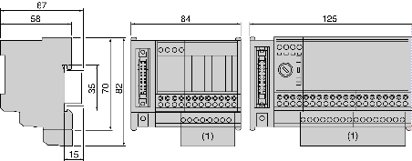
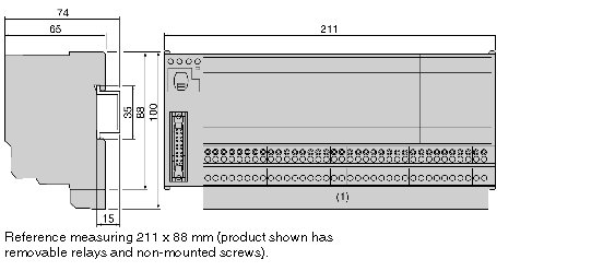
The illustration below shows the dimensions (in mm) of the products: ABE-7H••R1•, ABE-7H••R5•, ABE-7H••R2•, ABE-7H••S21, ABE-7H16R3•, ABE-7S08S2B0, ABE-7R••S1••, ABE-7R08S210.
(1) 
Dimension with additional shunt terminal block ABE-7BV20 or ABE-7BV10.
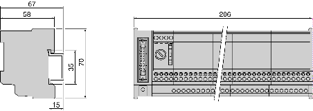
The illustration below shows the dimensions (in mm) of the products: ABE-7H16S43, ABE-7S16E2••, ABE-7S08S2B1, ABE-7S16S2B•, ABE-7H16F43•, ABE-7R16S21.
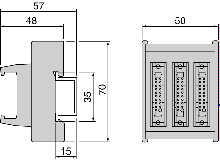
The illustration below shows the dimensions (in mm) of the product ABE-7ACC02.
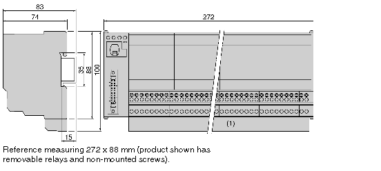
The illustration below shows the dimensions (in mm) of the products: ABE-7R16T2•• and ABE-7P16T2••.
(1) 
Dimension with additional shunt terminal block ABE-7BV20 or ABE-7BV10.
The illustration below shows the dimensions (in mm) of the products: ABE-7R16T3•• and ABE-7P16T3••.
(1) 
Dimension with additional shunt terminal block ABE-7BV20 or ABE-7BV10.
Mounting
The TELEFAST 2 bases are mounted on 35-mm wide DIN mounting rails.
WARNING
UNEXPECTED EQUIPMENT OPERATION
Install the input adaptation bases ABE-7S16E2E1 and static output adaptation bases ABE-7S••S2B• lengthways and horizontally to prevent the device from overheating and unexpected operation.
Failure to follow these instructions can result in death, serious injury, or equipment damage.