|
|
(Original Document)
|

|
Number
|
Description
|
|---|---|
|
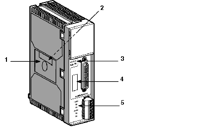
1
|
Label giving the characteristics of the safety outputs (on left-hand side).
|
|
2
|
Label giving the module reference number (on right-hand side).
|
|
3
|
External module supply marking.
|
|
4
|
Unmarked area for user identification.
|
|
5
|
Front panel label for marking of safety outputs.
|
|
Function
|
Terminals
|
|---|---|
|
External module power supply
|
A1-A2
|
|
System contact (+)
|
S01-S02, S11-S12, S21-S22, S31-S32, S41-S42, S51-S52, S61-S62, S71-S72, S81-S82, S91-S92, S101-S102, S111-S112
|
|
System contact (-)
|
S121-S122, S131-S132,S141-S142, S151-S152, S161-S162, S171-S172, S181-S182, S191-S192, S201-S202, S211-S212, S221-S222, S231-S232
|
|
Single and double contact selection
|
B1
|
|
Reactivation
|
S33-S34
|
|
Feedback loop
|
Y1-Y2
|
|
Reactivation input monitoring
|
Y3-Y4
|
|
Safety output supply
|
13-14, 23-24
|