|
Reflex function block: PWM (Pulse Width Modulation)
|
|
|
(Original Document)
|
|
Name
|
Meaning
|
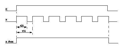
Illustration
|
|---|---|---|
|
E
|
Block's input.
|
 |
|
x
|
Block's physical output.
|
|
|
x Aux
|
Block's internal auxiliary output (control output).
|
|
Phase
|
Description
|
|---|---|
|
1
|
On the rising edge of input E :
|
|
2
|
On the low status of input E:
Note: if t2i (high status of period t1i) is higher than or equal to t1i, output x continually keeps the high status.
|

|
Characteristic
|
Value
|
|
Time Base
|
0.1 ms
|
|
F max
|
2 KHz
|
|
t1i (period)
|
0.1*(5 to 65535)
|
|
t2i (time on)
|
0.1*(2 to 65534)
|
|
t1
|
Frequency
|
Step
|
Number of steps
|
Duty Cycle min
|
Duty Cycle max
|
|
5
|
2 KHz
|
20%
|
4
|
20%
|
80%
|
|
10
|
1 KHz
|
10%
|
9
|
10%
|
90%
|
|
100
|
100 Hz
|
1%
|
99
|
1%
|
99%
|
|
1000
|
10 Hz
|
0.1%
|
999
|
0.1%
|
99.9%
|
|
10000
|
1 Hz
|
0.01%
|
9999
|
0.01%
|
99.99%
|
|
65535
|
0.15 Hz
|
0.0015%
|
65534
|
0.0015%
|
99.9985%
|