|
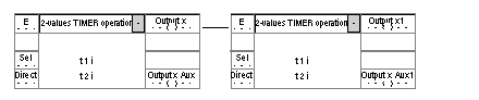
Reflex function block: 2 value operation timer
|
|


|
(Original Document)
|
|
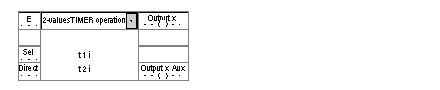
Reflex function block: 2 value operation timer
|
|
|
(Original Document)
|
|
Name
|
Meaning
|
|---|---|
|
E
|
Timer input.
|
|
Sel
|
Selection of time-out t1i or t2i.
|
|
Direct
|
Selection of block (for string operation).
|
|
x
|
Timer's physical output.
|
|
x Aux
|
Block's internal auxiliary output.
|
|
Illustration
 |
|
|
Phase
|
Description
|
|---|---|
|
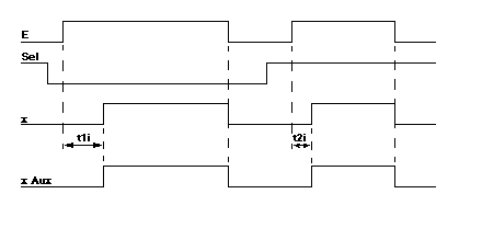
1
|
On the rising edge of the E input, a time-out corresponding to the status of input Sel is launched.
|
|
2
|
When the time-out is over, the x and x Aux outputs change to 1.
If the high status of input E lasts less time than the selected time-out, output x stays at 0.
|
|
Phase
|
Description
|
|---|---|
|
1
|
On the rising edge of the E input of the first block a time-out is launched, corresponding to:
Note: Two blocks must not simultaneously have their Direct inputs set to 0.
|
|
2
|
When the time-out is over, the x and x Aux outputs change to 1.
If the high status of the E input of the first block lasts less time than the selected time-out, output x stays at 0.
|
|
3
|
The x output changes to 0 on the falling edge of the E input .
|
|
Note:
|
|