|
Reflex function block: Operation-idle timer
|
|


|
(Original Document)
|
|
Reflex function block: Operation-idle timer
|
|
|
(Original Document)
|
|
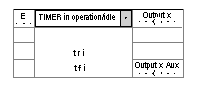
Name
|
Meaning
|
Illustration
|
|---|---|---|
|
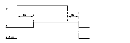
E
|
Timer input.
|
 |
|
x
|
Timer's physical output.
|
|
|
x Aux
|
Block's internal auxiliary output.
|
|
Phase
|
Description
|
|---|---|
|
1
|
On the rising edge of the E input (on-delay) , time-out tri is launched (time base of 0.1ms).
|
|
2
|
When time-out tri is over, the x output changes to 1.
If the high status of input E lasts less time than tri, output x stays at 0.
|
|
3
|
On the falling edge of the E input (off-delay) , time-out tfi is launched (time base of 0.1ms).
|
|
4
|
When time-out tfi is over, the x output changes to 0.
During time-out tfi, if the low status of input E lasts less time than tfi, output x stays at 1.
|
|
Note: The x Aux output is at 1 as long as input E or output x is at 1.
|
|