At a Glance
The compatibility between sensors and discrete module inputs depends on the type of sensor used.
Similarly, the compatibility between pre-actuators and discrete module outputs depends on the type of pre-actuator used.
Sensor/Input Compatibility
The following table presents the compatibility between 3-wire sensors and 24 VDC and 48 VDC inputs.
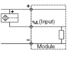
3-wire sensors and IEC 61131-2 compliant type 3 positive logic (sink) inputs: all 3-wire PNP inductive or capacitive proximity sensors and photo-electric detectors which have an operating voltage of 24 VDC and 48 VDC are compatible with all positive logic inputs. |
 |
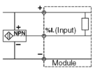
3-wire sensors and negative logic (source) inputs: all 3-wire NPN inductive or capacitive proximity sensors and photo-electric detectors which have an operating voltage of 24 VDC and 48 VDC are compatible with all negative logic inputs. |
 |
The following table presents the compatibility between 2-wire sensors and 24 VDC and 48 VDC inputs.
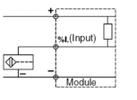
2-wire sensors and IEC 61131-2 compliant type 1 positive logic (sink) inputs: all proximity sensors or other 2-wire sensors with an operating voltage of 24 VDC and 48 VDC and with the characteristics described in the next table are compatible with all positive logic 24 VDC inputs. |
 |
2-wire sensors and negative logic (source) inputs: all proximity sensors or other 2-wire sensors with an operating voltage of 24 VDC are compatible with all negative logic 24 VDC inputs. |
 |
Compatibility between 2-wire sensors and 24/48 VAC and 120 VAC inputs:
All IEC 60947-5-2 compliant 2-wire AC proximity sensors able to withstand 100...120 VAC are compatible with all IEC 61131-2 type 1 and type 3 compliant 110...20 VAC inputs.
The following tables provide a summary of compatibility between sensors and discrete input/output module inputs.
Types of proximity sensor |
Types of input |
|||
|---|---|---|---|---|
24 VDC Positive logic |
48 VDC Type 1 Positive logic |
24 VDC Type 3 Positive logic |
24/48 VDC Negative logic |
|
All PNP-type 3-wire (DC) proximity sensors |
X |
X |
X |
- |
All NPN-type 3-wire (DC) proximity sensors |
- |
- |
- |
X |
Telemecanique or other brand 2-wire (DC) proximity sensors with the following characteristics:
|
- |
X |
X |
- |
Telemecanique or other brand 2-wire (DC) proximity sensors with the following characteristics:
|
X |
X |
X |
- |
X compatible - not compatible DC DC voltage operation |
||||
Types of proximity sensor |
Types of input |
||
|---|---|---|---|
24 VAC Type 1 |
48 VAC Type 3 |
100-120 VAC Type 3 |
|
2-wire (AC/DC) proximity sensor (see note) |
X |
X |
X |
2-wire (AC) proximity sensor |
X |
X |
X |
X compatible AC AC voltage operation AC/DC AC or DC voltage operation NOTE: 24 VDC inputs can be used in
positive (sink) or negative (source) logic but are not IEC compliant.
|
|||
Compatibility of Pre-Actuators with Outputs
Compatibility of DC Pre-actuators with Outputs:
Comply with the output’s maximum current and maximum switching frequency as specified in the module characteristics.
I max = I nominal + I leakage
Given that:
I nominal = Current required to operate by the pre-actuator
I leakage = Maximum leakage current in idle output state
Compatibility of Tungsten Filament Lamps and Static Outputs (Static Current):
For outputs with protection against short circuits, the maximum power of the tungsten filament lamps specified in the module characteristics must comply. If not, the lamp’s pick-up current might cause a tripped output at the time of power-up.
Compatibility of AC Pre-actuators and Relay Outputs:
Inductive AC pre-actuators have a pick-up current of up to 10 times their holding current for a duration of 2/F seconds (F = alternating current frequency). Relay outputs are therefore set to withstand these conditions (AC14 and AC15). The table of characteristics for relay outputs gives the maximum authorized running power (in AV) according to the number of operations.
| CAUTION | |
|---|---|


