At a Glance
The BMX DDM 16022 module is fitted with a removable 20-pin terminal block for the connection of eight input channels and eight output channels.

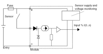
Input Circuit Diagram
The following diagram shows the circuit of a direct current input (positive logic).

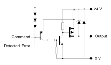
Output Circuit Diagram
The following diagram shows the circuit of a direct current output (positive logic).

Module Connection
| DANGER | |
|---|---|
| CAUTION | |
|---|---|
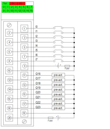
The following diagram shows the connection of the module to the sensors and pre-actuators.

power supply: 24 VDC
input fuse: fast blow fuse of 0.5 A
output fuse: fast blow fuse of 6.3 A
pre-act: pre-actuator
Sensor Power Outage
After a power sensor outage, if the check box is not selected in the module configuration screen then the digital input can stay active.
| WARNING | |
|---|---|
To access the check box, refer to chapter How to Modify the External Power Supply Error Monitoring Parameter.
After the sensor power outage, the I/O (red) LED of the module switches on and the last recorded position of the sensor is displayed by the input channel status LED's.
| WARNING | |
|---|---|


