The BMX DDI 3232 is fitted with a removable 40-pin terminal
block for the connection of thirty-two input channels.
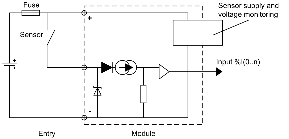
Input Circuit Diagram
The following diagram shows the circuit of a direct current
input (positive logic).
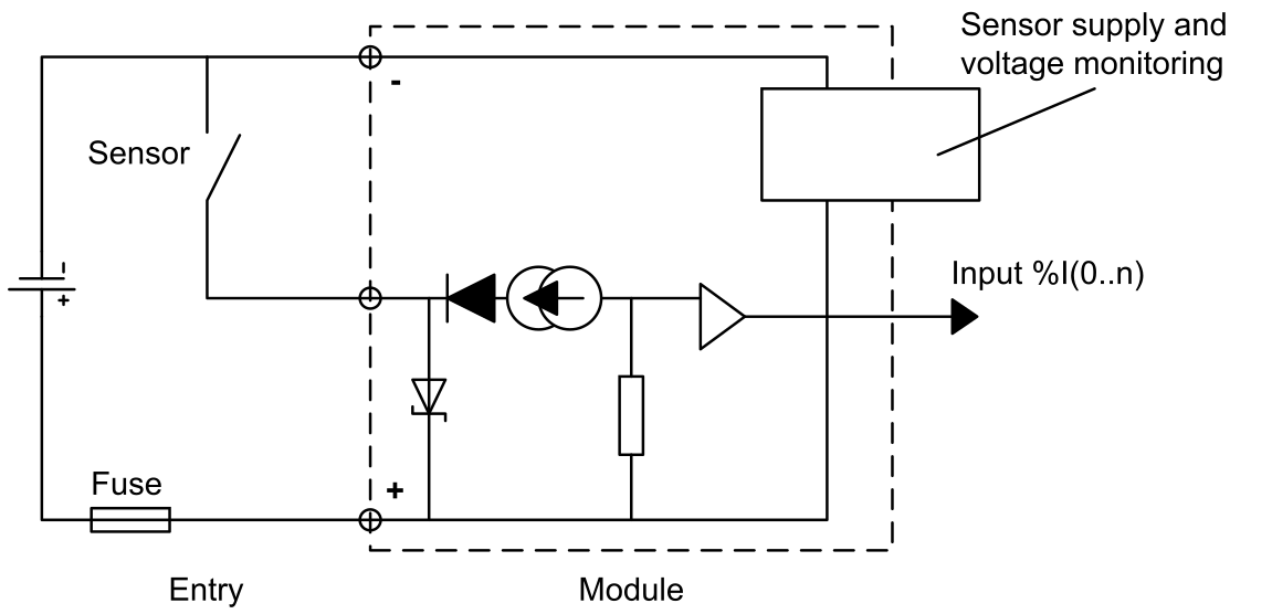
The following diagram shows the circuit of a direct current
input (negative logic).
Module Connection
DANGER
HAZARD OF ELECTRICAL SHOCK, EXPLOSION OR ARC FLASH
Switch off the sensor and pre-actuator voltages before
connecting or disconnecting the module.
Failure to follow these instructions will result in death or serious injury.
WARNING
EQUIPMENT DAMAGE
Do not connect SPS A/B terminal to more than
one power supply.
In case of multiple power supplies in the same group of channels,
disconnect SPS A/B terminal and disable the power
supply monitoring function.
Failure to follow these instructions can result in death, serious injury, or equipment damage.
CAUTION
LOSS OF INPUT FUNCTION
Install the correct type of fuse with the correct rating.
Failure to follow these instructions can result in injury or equipment damage.
The following diagrams show the
connection of the module to the sensors:
Positive logic (sink)
Negative logic (source)
1 fast blow fuse of 0.5A
2 Sensor power supply (SPS)
12 VDC/24 VDC
The following diagram shows an example of mixed sink/source
input:
1 fast blow fuse of 0.5A
2 Sensor power supply
(SPS) 12 VDC/24 VDC
NOTE: In the above example,
inputs of group A are in positive or negative logic (sink or
source), whereas inputs of group B are only in positive logic
(sink). SPS A and SPS B terminals are not connected and power supply monitoring should be
disabled for both groups.
Sensor Power Outage
After a power sensor
outage, if the Supply monitoring check box is not selected in the module configuration
screen then the digital input can stay active.
WARNING
DIGITAL INPUT STATE INACTIVE AFTER A SENSOR POWER OUTAGE
Do not click to clear the Supply
monitoring check box in the module configuration
screen to guarantee the digital input state inactive after sensor
power outage.
Failure to follow these instructions can result in death, serious injury, or equipment damage.
After the sensor power
outage, the I/O (red) LED of the module switches on and the last recorded
position of the sensor is displayed by the input channel status LED's.
WARNING
CHANNEL LED INFORMATION NOT MATCHING SENSORS POSITION
After a sensor power outage:
The I/O error LED is on
Do not take into account the input LEDs information (they show
the last recorded position of the sensors, not their real positions)
Check the real positions on the sensors.
Failure to follow these instructions can result in death, serious injury, or equipment damage.