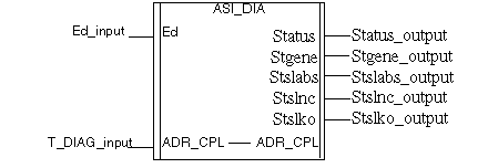
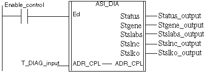
|
Description
|
|
|
(Original Document)
|


|
Name
|
Type
|
Description
|
|
ED
|
EBOOL
|
DFB activation bit
if ED=0, the AS-Interface bus is not monitored
NOTE: when ED=1, we can't open the TSXSAY1000 Debug screen from Control Expert module Editor |
|
Name
|
Type
|
Description
|
|
ADR_CPL
|
T_COM_ASI_DIAG
|
Adress of the AS-Interface Master Channel (IODDT)
|
 CAUTION CAUTION |
|
UNEXPECTED EQUIPMENT BEHAVIOR
T_DIAG_output must not be connected
Failure to follow these instructions can result in injury or equipment damage.
|
|
Name
|
Type
|
Role
|
Description
|
|
STATUS
|
WORD
|
Error Type
|
The next bits indicate the type of detected error:
|
|
STGENE
|
WORD
|
Module or bus error
|
Detail of the module or bus error:
|
|
STSLABS
|
ARRAY [0..3] of WORD
|
List of absent slaves
|
STSLABS[0] slaves 0A to 15A:
STSLABS[1]: slaves 16A to 31A:
STSLABS[2]: slaves 0B to 15B:
STSLABS[3]: slaves 16B to 31B:
Default values = 0
|
|
STSLNC
|
ARRAY [0..3] of WORD
|
List of not configured slaves
|
STSLNC[0]: slaves 0A to 15A:
STSLNC[1]: slaves 16A to 31A:
STSLNC[2]: slaves 0B to 15B:
STSLNC[3]: slaves 16B to 31B:
Default values = 0
|
|
STSLKO
|
ARRAY [0..3] of WORD
|
List of slaves with error(s)
|
STSLKO[0]: slaves 0A to 15A:
STSLKO[1]: slaves 16A to 31A:
STSLKO[2]: slaves 0B to 15B:
STSLKO[3]: slaves 16B to 31B:
Default values = 0
|
|
Parameter
|
Data type
|
Meaning
|
|
AREA_NR
|
WORD
|
Automation area to be monitored.
This WORD specifies which area will be monitored by the diagnostics EFB.
It is advisable to assign the numbers according to the functional module.
AREA_NR can be a value from 0 to 15.
The standard value is 0.
Example:
Cutting: No.1
Milling: No. 2
Thread cutting: No. 3
In the example, AREA_NR must have the value 1, 2 ou 3, so that they can recognize the error affected area.
|
|
OPT_CTRL
|
BOOL
|
This bit specifies whether a diagnostic will request a user acknowledgement.
0: no user acknowledgement required
1: user acknowledgement required
The standard value is 0.
|
|
Standard symbol
|
Type
|
Access
|
Meaning
|
Number
|
Rank
|
Bit
|
EXCH
|
|
CH_ERROR
|
BOOL
|
R
|
Channel error
|
%I
|
ERR
|
|
IMP
|
|
FLT_SLAVES_0A_15A
|
INT
|
R
|
Slave error 0A to 15A
|
%IW
|
0
|
|
IMP
|
|
FLT_SLAVES_16A_31A
|
INT
|
R
|
Slave error 16A to 31A
|
%IW
|
1
|
|
IMP
|
|
FLT_SLAVES_0B_15B
|
INT
|
R
|
Slave error 0B to 15B
|
%IW
|
2
|
|
IMP
|
|
FLT_SLAVES_16B_31B
|
INT
|
R
|
Slave error 16B to 31B
|
%IW
|
3
|
|
IMP
|
|
STS_IN_PROGR
|
BOOL
|
R
|
Status parameter read in progress
|
%MW
|
0
|
X0
|
SYS
|
|
STS_ERR
|
BOOL
|
R
|
Error while reading channel status
|
%MW
|
1
|
X0
|
SYS
|
|
CH_FLT
|
INT
|
R
|
Channel errors
|
%MW
|
2
|
|
STS
|
|
SLAVE_FLT
|
BOOL
|
R
|
1 in case of one error slave
|
%MW
|
2
|
X1
|
STS
|
|
ASI_CONF_FLT
|
BOOL
|
R
|
Physical configuration different from logical configuration
|
%MW
|
2
|
X3
|
STS
|
|
INTERNAL_FLT
|
BOOL
|
R
|
Internal error : channel inoperative
|
%MW
|
2
|
X4
|
STS
|
|
CONF_FLT
|
BOOL
|
R
|
Hardware or software configuration error
|
%MW
|
2
|
X5
|
STS
|
|
COM_FLT
|
BOOL
|
R
|
Bus communication error
|
%MW
|
2
|
X6
|
STS
|
|
SLAVE_0_PRESENT
|
BOOL
|
R
|
Slave 0 present on the bus
|
%MW
|
3
|
X1
|
STS
|
|
ASI_SUPPLY_FLT
|
BOOL
|
R
|
AS-Interface supply error
|
%MW
|
3
|
X6
|
STS
|
|
OFFLINE_MODE_ACTIVE
|
BOOL
|
R
|
Offline mode active
|
%MW
|
3
|
X7
|
STS
|
|
DATA_EXCHANGE_OFF
|
BOOL
|
R
|
Data exchange inactive
|
%MW
|
3
|
X8
|
STS
|
|
PERIPH FAULT
|
BOOL
|
R
|
Peripheral error on a bus device
|
%MW
|
3
|
X9
|
STS
|
|
LDS_0A_15A
|
INT
|
R
|
List of detected slaves 0A to 15A
|
%MW
|
4
|
|
STS
|
|
LDS_16A_31A
|
INT
|
R
|
List of detected slaves 16A to 31A
|
%MW
|
5
|
|
STS
|
|
LDS_0B_15B
|
INT
|
R
|
List of detected slaves 0B to 15B
|
%MW
|
6
|
|
STS
|
|
LDS_16B_31B
|
INT
|
R
|
List of detected slaves 16B to 31B
|
%MW
|
7
|
|
STS
|
|
MASTER_TYPE
|
INT
|
R
|
AS-Interface Master Type
|
%KW
|
0
|
|
CONST
|
|
LPS_0A_15A
|
INT
|
R
|
List of projected (configured) slaves 0A to 15A
|
%KW
|
1
|
|
CONST
|
|
LPS_16A_31A
|
INT
|
R
|
List of projected (configured) slaves 16A to 31A
|
%KW
|
2
|
|
CONST
|
|
LPS_0B_15B
|
INT
|
R
|
List of projected (configured) slaves 0B to 15B
|
%KW
|
3
|
|
CONST
|
|
LPS_16B_31B
|
INT
|
R
|
List of projected (configured) slaves 16B to 31B
|
%KW
|
4
|
|
CONST
|