|
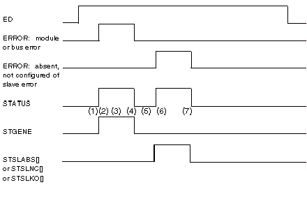
How the ASI_DIA Function Block works
|
|
|
(Original Document)
|

|
Phase
|
Description
|
|
1
|
A Module or Bus error is registered by the DFB in case of a break in the AS-Interface supply, bit 0 in STATUS and bit 2 in STGENE are set to 1.
|
|
2
|
A slave with 0 address is detected on the AS-Interface bus, bit 1 in STGENE is set to 1.
|
|
3
|
AS-Interface power is restored, but the Module or Bus error is not erased because a slave with 0 address is still detected on the AS-Interface bus.
|
|
4
|
The slave with 0 address is no longer detected on the AS-Interface bus, the error has disappeared. The STATUS and STGENE words are set to 0.
|
|
5
|
An Absent Slave(s), Not configured slave(s) or Error Slave(s) error is built into the STATUS word (bit = 1, 2 or 3) and bit 10 of STSLABS[0], STSLNC[0] or STSLKO[0] or STSLKO[0] is set to 1 indicating that AS-Interface slave 10 is in error.
|
|
6
|
AS-Interface slave 14 is disconnected, only bit 14 of STSLABS[0], STSLNC[0] or STSLKO[0] is set to 1.
|
|
7
|
AS-Interface slaves 10 and 14 are again present on the AS-Interface Bus. Bit 1 of STATUS is set to 0 and STSLABS[0], STSLNC[0] or STSLKO[0] are set to 0.
|