If the REACT input is "0", the internal counter will be started.
When the preset time at the DTIME input has expired, the ERR output will display an error that remains active until REACT becomes "1", STOP becomes "1", or diagnostics is deactivated.
If the tolerance time DTIME is entered as "0", an error message is displayed as soon as an error situation occurs.
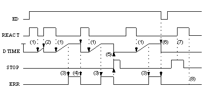
The timing diagram provides an example for the processing of reaction diagnostics.
Reaction diagnostics timing diagram
(1)
If REACT is "0", the internal time will be started.
(2)
If REACT becomes "1", the internal time is stopped and reset.
(3)
If the internal time reaches the DTIME value, an error will be reported.
(4)
If REACT becomes "1", the error will be cancelled and the internal time is stopped and reset.
(5)
If STOP becomes "1", the error will be cancelled and the internal time is stopped and reset.
(6)
When the enable signal ED is "0", the error is cancelled and the internal time is stopped and reset.
(7)
If REACT is "1" and STOP is "1", the reaction diagnostic is not started.
(8)
If REACT subsequently becomes "0", the internal time is not started, even if STOP is "0" again. 