Description
(Original Document)
Function description
The D_LOCK function block is used for locking Diagnostics and to enable the action.
The locking diagnostics are activated when the input with the TRIGR signals becomes active.
In control networks the trigger signal TRIGR (e.g. step counter, manual key) does not necessarily initiate the execution of an action directly, but is generally combined with locks from the process. It is therefore possible that the action ACT only becomes active after a time delay or not at all. It is the task of lock diagnostics to check whether UNLOCK is enabled within a tolerance time DTIME when the trigger signal is active. In this case the lock diagnostics enables the action ACT. In this instance the trigger signal TRIGR must be active throughout the entire time. If the lock enable UNLOCK does not appear within the time period, an error situation occurs (lock not freed). In this instance the action output ACT does not become active and the error output ERR is set. In addition, the logic at the UNLOCK input is analyzed and the error is entered in the error buffer. This error message is terminated when the trigger signal TRIGR is inactive or the lock enable UNLOCK becomes active.
The D_LOCK function block contains a REACT input that enables the ACT output to be switched off or prevents its activation without a locking error being reported.
NOTE: Please ensure that the REACT input is not negated. To switch off the action, REACT must have the value "1".
The lock diagnostics terminate with an active action output ACT.
Monitoring is carried out cyclically. The activation of the diagnostics and thereby the distribution of the cycle load can be achieved through the enable signal ED. The ED enable signal refers only to the activation of the diagnostics and has no effect on the ACT output.
NOTE: Do not use diagnostic EFBs in DFBs.
EN and ENO can be configured as additional parameters.
Representation in FBD
Representation:
Representation in LD
Representation:
Representation in IL
Representation:
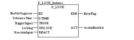
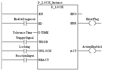
CAL D_LOCK_Instance (ED:=EnableDiagnosis,
    DTIME:=ToleranceTime, TRIGR:=TriggerSignal,
    UNLOCK:=Locking, REACT:=ReactionInput,
    ERR=>ErrorFlag, ACT=>ActionEnabled)
Representation in ST
Representation:
D_LOCK_Instance (ED:=EnableDiagnosis,
    DTIME:=ToleranceTime, TRIGR:=TriggerSignal,
    UNLOCK:=Locking, REACT:=ReactionInput,
    ERR=>ErrorFlag, ACT=>ActionEnabled) ;
Description of parameters
Description of the input parameters:
Parameter
Data type
Meaning
ED
Enable diagnostics
DTIME
Tolerance time
TRIGR
BOOL
Trigger signal
UNLOCK
BOOL
Lock
REACT
BOOL
Reaction input
Description of the output parameters:
Parameter
Data type
Meaning
ERR
BOOL
Error message; 0: no error; 1: Error
ACT
BOOL
Action output
Public variables
Description of the public variables:
Parameter
Data type
Meaning
AREA_NR
Automation area to be monitored.
This byte specifies which area will be monitored by the diagnostic EFB.
It is advisable to assign the numbers according to the functional modules.
Values: 0 ... 15. The standard value is 0.
Example:
  • Cutting: No. 1
  • Milling: No. 2
  • Thread cutting: No. 3
In the example AREA_NR must have the value 1, 2 or 3, so that they can recognize the error affected area.
OP_CTRL
BOOL
This bit specifies whether a diagnostic event will request a user acknowledgement.
  • 0: no user acknowledgement required
  • 1: user acknowledgement required
The standard value is 0.