|
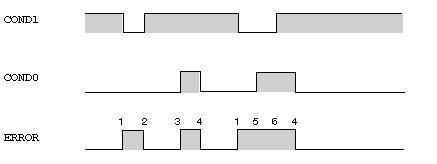
Detailed description of the operation of the ALRM_DIA function block
|
|
|
(Original Document)
|

|
Phase
|
Description
|
|---|---|
|
1
|
An error is detected when the input COND1 is set to 0.
|
|
2
|
The error is reset when the input COND1 is set to 1.
|
|
3
|
An error is detected when the input COND0 is set to 1.
|
|
4
|
The error is reset when the input COND0 is set to 0.
|
|
5
|
An error is not detected when the input COND0 is set to 1, as an error already exists.
|
|
6
|
The error is not reset when the input COND1 is set to 1, as the input COND0 remains at 1.
|