|
Detailed description of the operation of the MV_DIA function block
|
|
|
(Original Document)
|

|
Phase
|
Description
|
|---|---|
|
1
|
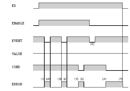
When the EVENT input is different from the VALUE public variable (ENABLE = 1), a fault is detected.
|
|
2
|
The ERROR output changes to 0 when the EVENT input takes on the values of the VALUE public variable.
|
|
3
|
A fault is detected when the EVENT input becomes unstable.
This type of fault appears after the status of EVENT input changes twice in the same monitoring cycle.
The EVENT input unstable fault (bit 8 of Status word goes to 1) , becomes an EVENT different from VALUE fault (bit 0 of Status word goes to 1) if there are more than 1000 PLC cycles before a new fault is detected.
The EVENT input unstable fault disappears if there are more than 1000 PLC cycles, and also if the EVENT input is always equal to the value specified by VALUE.
|
|
4
|
A fault is detected when COND input is anything other than 1.
|
|
5
|
ERROR output changes to 0 when COND input takes on the value of 1.
|
|
6
|
EVENT input is different from the VALUE public variable: there is no fault as ENABLE input = 0.
|
|
7
|
ERROR output changes to 0 when ED input takes on the value of 0.
|

|
Phase
|
Description
|
|---|---|
|
1
|
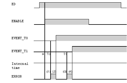
A fault is detected when the EVENT_T0 input does not change to 1 during T0 time.
|
|
2
|
ERROR output changes to 0 when EVENT_T0 input takes on the value of 1.
|
|
3
|
A fault is detected when EVENT_T1 input has not changed to 1 during T1 time.
|
|
4
|
ERROR output changes to 0 when EVENT_T1 input takes on the value of 1.
|

|
Phase
|
Description
|
|---|---|
|
1
|
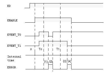
A fault is detected when EVENT_T0 input has not remained at 1 after T0 time.
|
|
2
|
ERROR output changes to 0 when EVENT_T0 input takes on the value of 1.
|
|
3
|
A fault is detected when EVENT_T1 input has not remained at 1 after T1 time.
|
|
4
|
ERROR output changes to 0 when ENABLE input changes to 0.
|