|
Description
|
|
|
(Original Document)
|


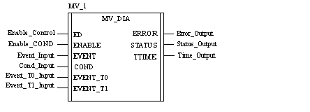
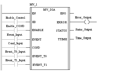
CAL MV_1 (ED := Enable_Control, ENABLE := Enable_COND, EVENT := Event_Input, COND := Cond_Input, EVENT_T0 := Event_T0_Input, EVENT_T1 := Event_T1_Input, ERROR => Error_Output, STATUS => Status_Output, TTIME => Time_Output)
MV_1 (ED := Enable_Control, ENABLE := Enable_COND, EVENT := Event_Input, COND := Cond_Input, EVENT_T0 := Event_T0_Input, EVENT_T1 := Event_T1_Input, ERROR => Error_Output, STATUS => Status_Output, TTIME => Time_Output);
|
Parameter
|
Type
|
Description
|
|---|---|---|
|
ED
|
DFB activation bit.
If ED = 0, the EVENT,EVENT_T0, EVENT_T1 and COND inputs are not monitored.
The default value is 0.
|
|
|
ENABLE
|
Monitor enable bit
If ENABLE = 0, only COND input is monitored.
If ENABLE = 1, the CONDand EVENT_T0, EVENT_T1 are monitored.
The default value is 0.
|
|
|
EVENT
|
Input bit to be monitored.
If the DFB is executed and ENABLE = 1, the DFB verifies that the EVENT input:
If this is not the case, the DFB will signal that there is a fault.
If ENABLE = 0, theEVENT input is not monitored.
The default value is 0.
|
|
|
COND
|
Input bit to be monitored.
The input bit to be monitored is set at 1, whatever the status of the ENABLE input.
If the DFB is executed and this bit changes to 0, the DFB will signal that there is a fault.
The default value is 1.
|
|
|
EVENT_T0
|
Exterior event associated with T0 time.
This (optional) parameter is a bit which must change from 0 to 1 before T0 time or in ENABLE = 1 format.
The default value is 1.
|
|
|
EVENT_T1
|
Exterior event associated with T1 time.
This (optional) parameter is a bit which must change from 0 to 1 before T1 time or in ENABLE = 1 format.
The default value is 1.
|
|
Parameter
|
Type
|
Description
|
|---|---|---|
|
ERROR
|
Fault bit
This bit is set to 1 as soon as a fault appears.
This bit is set to 0 if the ED input returns to 0 or if there is no longer an error.
|
|
|
STATUS
|
Fault type.
The following bits indicate the type of fault detected :
This word is set at 0 if there is no fault.
This word is set at 0 if the ED input returns to 0 or if there is no longer an error.
|
|
|
TTIME
|
Current time.
Word indicating the current time with a time base expressed in multiples of N x 100 ms
The N coefficient is defined by the BASE public variable.
TTIME is initialized at the PPRESET value, and starts to change on the rising edge of the ENABLE input.
It sets to 0, on the ENABLE falling edge.
If a fault is detected (caused by EVENT input), TTIME does not remain frozen:
|