This section describes the operation of counting input interfaces which are common to modules TSX CTY 2A, 4A and 2C.
Configuration: IA up/down counts, direction according to application
The figure below represents the counting signal applied to the IA ST_IA (%IWr.m.c.2.0) input.
In this configuration, the change of direction COUNT_DIR (%Ir.m.c.9) bit managed by the application determines direction of the up or down counting on the rising edges of the signal.
Configuration: IA up/down counts, direction according to IB
The following figure represents the counting signal applied to the IA and IB ST_IB (%IWr.m.c.2.1) inputs defining the counting direction.
Up/down counting is done on the rising edges of pulses received on IA input.
Configuration: IA up counts, IB down counts
The figure below represents the counting signal applied to IA input (in up counting) or to IB input (in down counting)
Pulses are taken into account by the up/down counter on the rising edges of the physical input in progress. IA input increments the up/down counter (upcounting) and IB input decrements it (downcounting). If pulses on the two inputs are simultaneous, the up/down counter does not change.
Configuration: incremental encoder
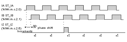
In this operating mode, physical inputs IA and IB are connected to an incremental encoder which supplies two out-of-phase signals of 90°. The extent to which inputs IA and IB are out of phase determines the direction of up/down counting.
The figure below represents the case of counting (IA ahead of IB).
NOTE: the incremental encoder also provides marker information on the IZ input.
This pulse on the IZ ST_IZ (%IWr.m.c.2.6) input enables an up/down counter to be preset.
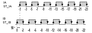
The figure below represents the case of down counting (IA behind IB).
Incremental encoder interface options
Several options are available on the configuration screen when an incremental encoder is connected:
|
If
|
Then
|
|
the line check is configured (encoder with RS 422 / 485 output),
|
the PLC indicates a fault when it detects a break in the encoder cable on one of the IA, IB or IZ physical inputs. It is then possible to start the application procedure which corresponds to the fault.
|
|
multiplication by 1 is configured,
|
up/down counting is done on rising edges of IB physical input (case shown: counting)
. |
|
multiplication by 4 is configured,
|
up/down counting is done on all the rising and falling edges of IA and IB physical inputs (case shown: down counting)
. |


