Each TSX CTY 2C module channel has four physical outputs: Q0, Q1, Q2 and Q3.
All outputs can be used in manual (discrete) mode. The state of these outputs is then set with commands sent by software. The associated language objects are described in the
implicit objects section.
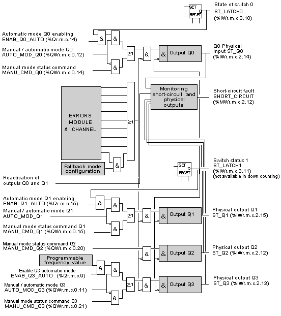
The physical outputs Q0 ST_Q0 (%IWr.m.c.2.14) or Q1 ST_Q1 (%IWr.m.c.2.15) can also be configured in automatic mode. The state of outputs Q0 and Q1 is then that of the counter outputs 0 and 1 respectively. Automatic mode is used to install reflex actions in the module, depending on the state of the up/down counter.
Q2 is actually an input/output which can be configured:
-
either as an enabling physical input IVal ST_IENAB (%IWr.m.c.2.2),
-
or as a physical output Q2 (in manual mode only).
The output Q3 ST_Q3 (%IWr.m.c.2.13) can be used:
Programmable frequency output enables an external synchronization marker to be used on several channels of modules.
The figure below shows the structure of module TSX CTY 2C physical outputs. The associated language objects are described in the
default objects section.
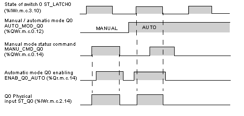
The time diagram below shows how outputs operate (using Q0 output as an example)

