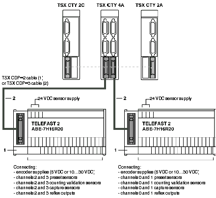
The TSX CTY 4A wiring is as follows. For a TSX CTY 2A or TSX CTY 2C module, only one TELEFAST is connected (channels 0 and 1).
NOTE: Using a discrete TELEFAST connection base is not compulsory, but advisable as it facilitates the connection of supplies, sensors and pre-actuators on to the auxiliary I/O.
(1) TSX DCP 102: 1 m in length,
TSX CDP 202: 2 m in length,
TSX CDP 302: 3 m in length,
(2) TSX CDP 053: 0.5 m in length,
TSX CDP 103: 1 m in length,
TSX CDP 203: 2 m in length,
TSX CDP 303: 3 m in length,
TSX CDP 503: 5 m in length.
Description of the different connection elements
This table shows the different connection elements according to address:
|
Number
|
Description
|
|
1
|
TELEFAST 2 connection base: ABE-7H16R20. This allows rapid connection of:
-
the 24 VDC supply for the sensors connected to the auxiliary I/O,
-
the encoder supply (if the counting sensor is of the encoder type),
-
the sensors onto the auxiliary I/O (preset, confirmation, capture),
-
the pre-actuators.
|
|
2
|
Stranded and clad TSX CDP •• 2 cable or connection cable
TSX CDP ••3.
|
NOTE: The ABE-7BV20 accessory (sold in inseparable quantities of 5) facilitates shared connection.
