|
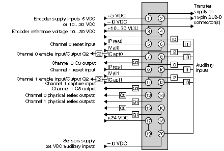
20-pin HE10 connector of a TSX CTY 2C module
|
|
|
(Original Document)
|

|
24 VDC signals
|
Pins
|
|---|---|
|
Channel 0 auxiliary input:
|
|
|
Preset IPres0
|
5
|
|
Confirmation IVal0/Output Q2
|
6
|
|
Capture ICapt0
|
7
|
|
Output Q3
|
8
|
|
Channel 1 auxiliary input:
|
|
|
Preset IPres1
|
9
|
|
Confirmation IVal1/Output Q2
|
10
|
|
Capture ICapt1
|
11
|
|
Output Q3
|
12
|
|
Channel 0 reflex output:
|
|
|
Output Q0
|
13
|
|
Output Q1
|
14
|
|
Channel 1 reflex output:
|
|
|
Output Q0
|
15
|
|
Output Q1
|
16
|
|
Supplies
|
Pins
|
|---|---|
|
Encoder supply:
|
|
|
+5 VDC
|
1
|
|
- 0 VDC
|
2
|
|
+10...30 VDC
|
3
|
|
Encoder reference voltage +10…30 VDC
|
4
|
|
Sensor supply:
|
|
|
+24 VDC
|
17 or 19
|
|
-0 VDC
|
18 or 20
|