|
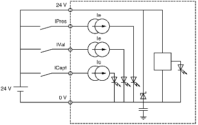
Auxiliary input characteristics (preset, confirmation, capture)
|
|
|
(Original Document)
|
|
Modules
|
TSX CTY 2A / 4A
|
TSX CTY 2C
|
||
|---|---|---|---|---|
|
Logic
|
Positive
|
Positive or negative
|
||
|
Nominal values
|
Voltage
|
24 VDC
|
24 VDC
|
|
|
Current
|
7 mA
|
8 mA
|
||
|
Sensor supply
(ripple included)
|
19...30 V (possible up to 34 V, limited to 1hr in 24)
|
|||
|
Thresholds
|
In state 1
|
Voltage
|
≥11 V
|
≥11 V
|
|
Current
|
> 6 mA (1)
|
> 6 mA (1)
|
||
|
In state 0
|
Voltage
|
≤ 5 V
|
≤ 5 V
|
|
|
Current
|
< 2 mA
|
< 2 mA
|
||
|
Sensor/pre-actuator voltage check threshold
|
OK
|
> 18 V
|
> 18 V
|
|
|
Fault
|
< 14 V
|
< 14 V
|
||
|
Sensor/pre-actuator voltage check response time
|
With a loss of 24V
|
< 2.5ms (4)
|
< 2.5ms (4)
|
|
|
With an increase of 24V
|
< 10 ms (4)
|
< 10 ms (4)
|
||
|
Input impedance
|
3.4kΩ
|
3.4kΩ
|
||
|
Response time
|
State 0 to 1
|
< 250 μs (3)
|
< 25 μs (3)
|
|
|
State 1 to 0
|
< 250 μs (3)
|
< 50 μs (3)
|
||
|
Type of inputs
|
Current ducts
|
Resistive
|
||
|
IEC 1131 conformity
|
Type 2
|
Type 2
|
||
|
2-wire proximity sensor compatibility (3)
|
Yes (all 2-wire proximity sensors at 24 VDC)
|
|||
|
3-wire proximity sensor compatibility (3)
|
Yes (all 3-wire proximity sensors at 24 VDC)
|
|||
