|
|
(Original Document)
|
|
Step
|
Action
|
|---|---|
|
1
|
Expand the Communication directory in the project browser.
Result::
 |
|
2
|
Right-click in the Networks sub-directory and select the New network option.
Result::
 |
|
3
|
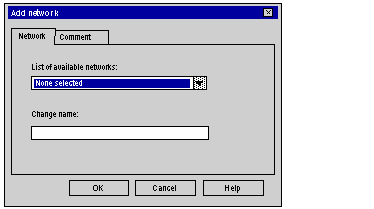
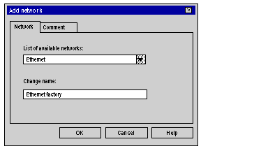
Select the network that you want to create from the list of available networks and give it a meaningful name.
Result: Example of an Ethernet network:
 Note: You can also add a comment, if you so desire, by clicking on the Comment tab.
|
|
4
|
Click OK and a new logic network is created.
Result: We have just created the Ethernet network that appears in the project browser
 Note: As you can see, a small icon indicates that the logic network is not associated with any PLC hardware. Furthermore, the small blue "v" sign indicates that the project needs to be rebuilt before it can be used in the PLC.
|