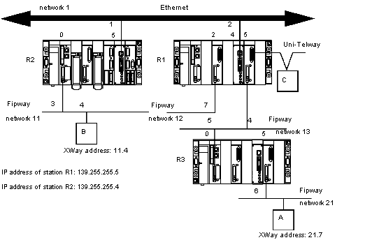
Each station must be configured in order to define the list of accessible networks.
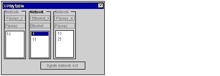
Configuration of Station R1
The module at slot 2 can only access network 12.
The module at slot 4 can only access network 1 and 11.
The module at slot 5 can access networks 13 and 21.
The bridge configuration of the station is therefore as follows:
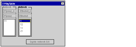
Configuration of Station R2
The module at slot 0 can only access network 11.
The module at slot 5 can access networks 1, 12, 13 and 21.
The bridge configuration of the station is therefore as follows:
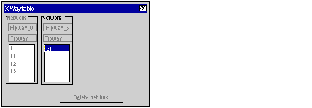
Configuration of Station R3
The module at slot 0 can access networks 13, 12, 1 and 11.
The module at slot 5 can only access network 21.
The bridge configuration of the station is therefore as follows:
To use the
communication function such as Read_VAR for ethernet exchange between stations, configure the TCP/IP Messaging in the Ethernet network
configuration screen. In the
Messaging tab, for each exchange set the IP address and target XWay address.
For example if station R3 needs to communicate with station B, in R1Messaging tab:
-
set the R2 IP address (139.255.255.4) in the field IP address, and
-
set the B XWay address (11.4) in the field XWay address.
The following illustration shows the R1
Messaging tab:
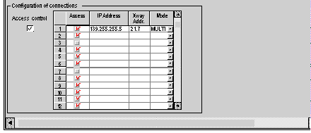
For another example if station B needs to communicate with station A, in R2, Messaging tab:
-
set the R1 IP address (139.255.255.5) in the field IP address, and
-
set the A XWay address (21.7) in the field XWay address.
The following illustration shows the R2
Messaging tab:
